Optical probe and optical pick-up apparatus

a technology applied in the field of optical probes and optical pickups, can solve the problems of failure to obtain micro spots, low light throughput efficiency, and low throughput efficiency of light passing through the probe, and achieve the effect of increasing the throughput efficiency of light wave passing through the core portion and small spot diameter

Inactive Publication Date: 2005-04-26
KK TOSHIBA
View PDF5 Cites 8 Cited by
  • Summary
  • Abstract
  • Description
  • Claims
  • Application Information

AI Technical Summary

Benefits of technology

[0008]An object of the present invention is to provide an optical probe capable of confining the light wave to a core portion so as to make the spot diameter very small and capable of sufficiently increasing the throughput efficiency of the light wave passing through the core portion.
[0044]According to the present invention, a light absorbing film is formed on that side surface of the core which is substantially perpendicular to the polarized direction of the light wave propagated through the core so as to eliminate the oozing of the light wave in the particular direction, thereby obtaining a micro spot light. Further, a transparent clad region is formed on that side surface of the core, which is parallel to the polarized direction of the light wave propagated through the core so as to increase the light throughput efficiency. In addition, the object of the present invention can be effectively achieved by effectively utilizing the construction that the TM mode and the TE mode differ from each other in the propagation loss relative to the presence of the light absorbing film and in the size of the spot diameter. It follows that it is possible to make the spot diameter very small and to increase the throughput efficiency of the light wave passing through the core.

Problems solved by technology

However, the optical probe of this kind gives rise to the problem that, because of the absorption by the metal coated on the side surface, the light throughput efficiency is very low.
In this case, however, the oozing of the light wave from the sharpened distal end portion of the optical fiber is increased, resulting in failure to obtain a micro spot.
As described above, the conventional optical probe having a metal coating applied to the side surface of the sharpened distal end portion of an optical fiber gives rise to the problems that the throughput efficiency of the light passing through the probe is very low and that it is impossible to obtain a desired micro spot unless the metal coating is not applied to the side surface.

Method used


Image

  • Optical probe and optical pick-up apparatus
  • Optical probe and optical pick-up apparatus
  • Optical probe and optical pick-up apparatus

Examples


Embodiment Construction

[0055]Some embodiments of the present invention in respect of an optical probe and an optical pick-up apparatus using the optical probe will now be described in detail with reference to the accompanying drawings.

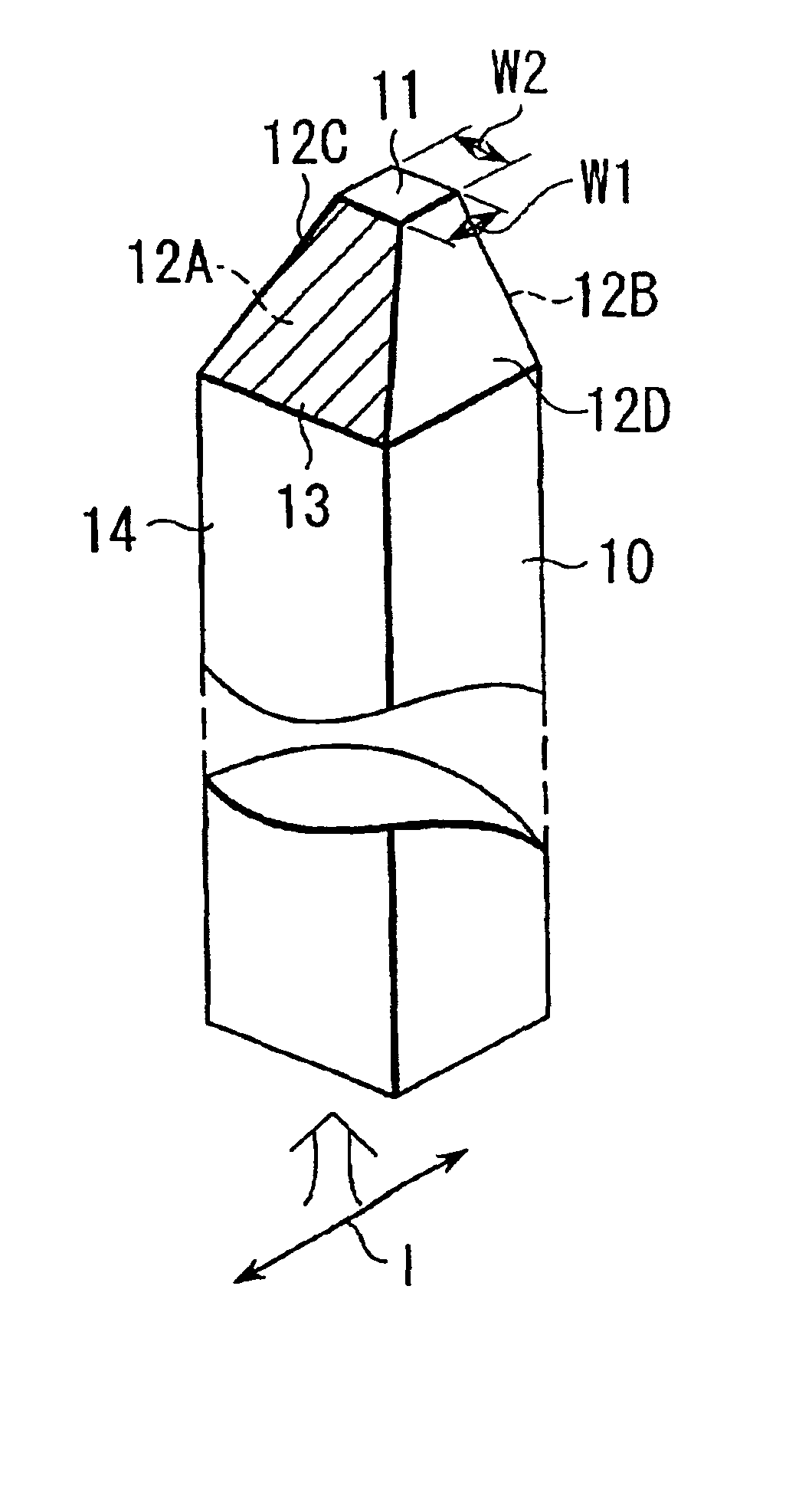
[0056]FIG. 1 is an oblique view schematically showing the construction of an optical probe according to a first embodiment of the present invention.

[0057]A reference numeral 10 shown in FIG. 1 represents a rod-like glass core rectangular in cross section, in which a light wave is guided. The distal end portion of the glass core 10 is worked pyramidal such that the distal end portion is gradually diminished from a rectangular base portion 14 of the core 10. The core 10 has a micro distal end face section 11 which is a rectangular shape. The micro distal end face section 11 has a first pair of opposing sides extending in the polarized direction I of the light wave propagated through the core 10 and also has a second pair of opposing sides extending in a direction perpendicular...


PUM

PropertyMeasurementUnit
width W2aaaaaaaaaa
wavelengthaaaaaaaaaa
refractive indexaaaaaaaaaa

Abstract

Disclosed is an optical probe for obtaining a micro spot light, comprising a rod-like glass body having a rectangular cross section as a core for propagating a light wave. The distal end portion of the glass body is gradually diminished toward the distal end so as to form a micro distal end face having a small diameter. The side surface of the distal end portion of the glass body in a direction perpendicular to the polarized direction of the light wave is coated with a light absorber formed of a metal film.

Description

CROSS-REFERENCE TO RELATED APPLICATIONS[0001]This application is based upon and claims the benefit of priority from the prior Japanese Patent Application No. 2000-277109, filed Sep. 12, 2000, the entire contents of which are incorporated herein by reference.BACKGROUND OF THE INVENTION[0002]1. Field of the Invention[0003]The present invention relates to an optical probe for obtaining a micro light spot and an optical pick-up apparatus using said optical probe.[0004]2. Description of the Related Art[0005]In recent years, an optical probe utilizing an optical near field is used for recording information in an optical disk with a resolution not higher than the diffraction-limited of light or for observing the surface of an object to be measured, as disclosed in, for example, publication 1 (S. Mononobe et al.: “Reproducible fabrication of a fiber probe with a nanometric protrusion for near-field optics”, Appl. Opt., Vol. 36, No. 8 (11997) pp. 1496-1500) and publication 2 (Y. Kim et al.; ...

Claims


Application Information

Patent Timeline
Patent Type & Authority Patents(United States)
IPC IPC(8): G02B6/24G11B7/22G11B7/135G01Q60/22G01Q80/00G02B6/122G11B7/00
CPCG02B6/241G11B7/22G11B7/1387G11B7/1384G11B7/00
Inventor HATAKOSHI, GENICHI
Owner KK TOSHIBA
Why Eureka
Try Eureka