Process And Apparatus For Modifying Bitumen

Active Publication Date: 2008-04-24
MATTHEWS
View PDF14 Cites 5 Cited by
  • Summary
  • Abstract
  • Description
  • Claims
  • Application Information

AI Technical Summary

Benefits of technology

[0007] An object of the present invention is to provide apparatus for modifying bitum

Problems solved by technology

The process of modifying bitumen by blowing is relatively slow.
It can also be inherently dangerous due to the presence of volatile hydrocarbons in any airspace within the bitumen modifying apparatus.
The process ma

Method used


Image

  • Process And Apparatus For Modifying Bitumen
  • Process And Apparatus For Modifying Bitumen

Examples


Embodiment Construction

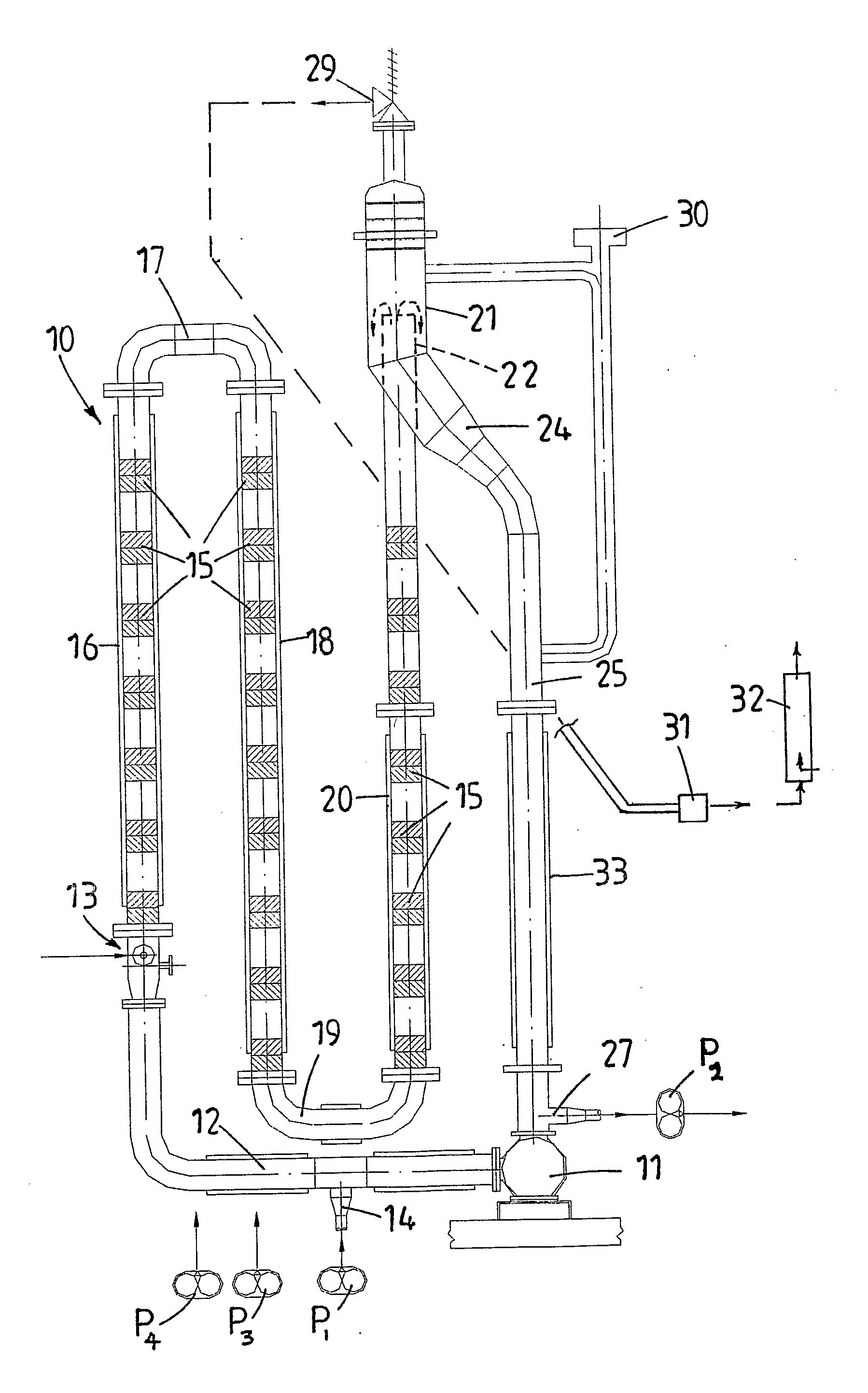
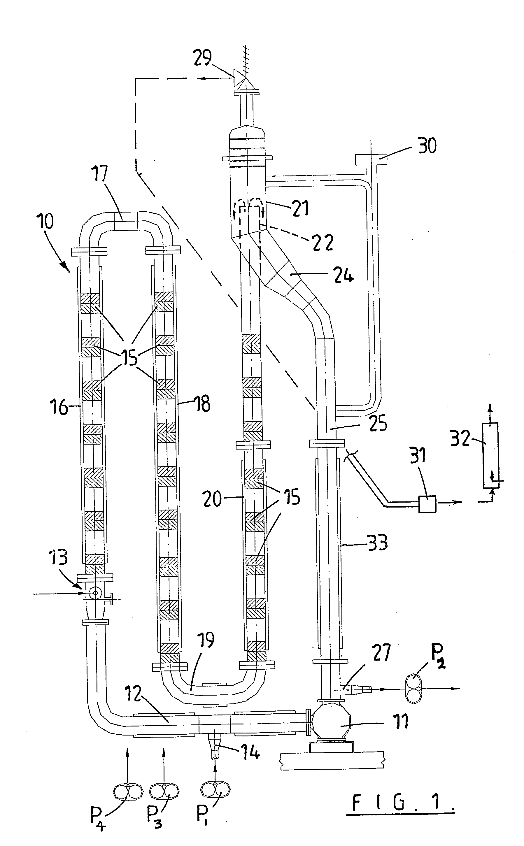
[0019] The following description relates to one preferred form of apparatus for carrying out the invention. Essentially the apparatus comprises a tube reactor 10 and in the more preferred form of the invention an apparatus which effectively comprises a single but multi-section tube reactor. More particularly, the tube reactor is in the form of a loop reactor.

[0020] The apparatus 10 includes a circulation pump 11, which is coupled by tube 12 to an air injection point 13, which includes an air flow controller. At a point between the pump 11 and the air injection inlet 13 there is provided an inlet 14 for the intake of bitumen into tube 12. The control unit of the apparatus will control a variable pump speed P1 to control the amount of bitumen being added into the reactor via inlet 14.

[0021] At initial start-up of the apparatus the reactor will be filled with bitumen prior to air injection commencing. Slowly the circulation pump 11 will be bought up to speed (when starting the appara...


PUM

PropertyMeasurementUnit
Pressureaaaaaaaaaa
Volumetric flow rateaaaaaaaaaa
Temperatureaaaaaaaaaa

Abstract

Apparatus for modifying bitumen. The apparatus includes a multi-section loop tube reactor A circulation pump (11) circulates bitumen in the reactor (10) and air is introduced at air injection point (13). Bitumen is introduced into the reactor (10) at inlet (14) by variable speed pump P1. A plurality of mixers (15) are located between the air injection point (13) and a head section (24) beyond which is an outlet (27) where modified bitumen is drawn off by variable speed pump P2.

Description

BACKGROUND TO THE INVENTION [0001] This invention relates to a process and apparatus for modifying bitumen. [0002] Modifying bitumen and more particularly modifying the properties of bitumen by oxidising the bitumen is known. Oxidised or so-called “blown bitumen” is obtained by blowing or passing air through the bitumen when the bitumen is at a very high temperature e.g. 200-350° C. typically 240 to 280° C. The resultant modified bitumen is harder i.e. has an increased softening temperature and viscosity at comparable temperatures. [0003] With use of appropriate reagents the properties of the bitumen can be modified further such that the bitumen viscosity is less temperature susceptible. These multi-grade bitumens are also known in the art. [0004] The process of modifying bitumen by blowing is relatively slow. It can also be inherently dangerous due to the presence of volatile hydrocarbons in any airspace within the bitumen modifying apparatus. The process may also result in signifi...

Claims


Application Information

Patent Timeline
IPC IPC(8): C08L95/00B01J19/18
CPCC10C3/04
Inventor MATTHEWS, JOHN
Owner MATTHEWS
Why Eureka
Try Eureka