Soller slit using low density materials

a low density, material technology, applied in the field of x-ray metrology, can solve the problems of poor transmission through the soller slit device, difficult control of the divergence, poor mechanical stability of very thin sheets, etc., and achieve the effect of increasing the transmission throughput efficiency and low density

Inactive Publication Date: 2005-12-22
BEDE
View PDF11 Cites 5 Cited by
  • Summary
  • Abstract
  • Description
  • Claims
  • Application Information

AI Technical Summary

Benefits of technology

[0012] In accordance with the present invention, the foregoing objectives are achieved by way of an X-ray Soller slit collimating device that uses lightweight, low density materials that are relatively inexpensive. The density of the material used is less than 6 g / cm3. The Soller slit device of the present invention provides an increased transmission throughput efficiency of greater than 60%, while maintaining a low divergence of less than 0.1°.

Problems solved by technology

However, because of the very nature of this type of radiation, it is often difficult to control its divergence.
Although these metal sheets can be made extremely thin, the mechanical stability of very thin sheets is not good enough for high precision X-ray work.
For example, any curling or rumpling of the sheets, which is common with metals, will result in poor transmission through the Soller slit device, and consequently unpredictable divergence.
These metal foil devices yield relatively low transmission efficiencies.
Moreover, the transmission efficiencies of such devices worsens as the required divergence is reduced (i.e., the quality of such devices' outputs becomes worse as their design constraints are made more restrictive).
However, the Soller slit described therein requires expensive ceramic materials processing to build, and is therefore less desirable for commercial applications.
One problem generally associated with Soller slit devices used for such commercial applications as X-ray diffractometry, however, is that they generally have relatively low transmission efficiencies and large divergence angles.
Thus, generally well over half of the X-ray radiation passing through the device is lost and unusable for measurements in the application in which the Soller slit is being employed.
This typical divergence angle is large, and negatively impacts the Soller slit's ability to effectively collimate x-ray radiation for many important commercial applications such as X-ray diffractometry.

Method used


Image

  • Soller slit using low density materials
  • Soller slit using low density materials
  • Soller slit using low density materials

Examples


Embodiment Construction

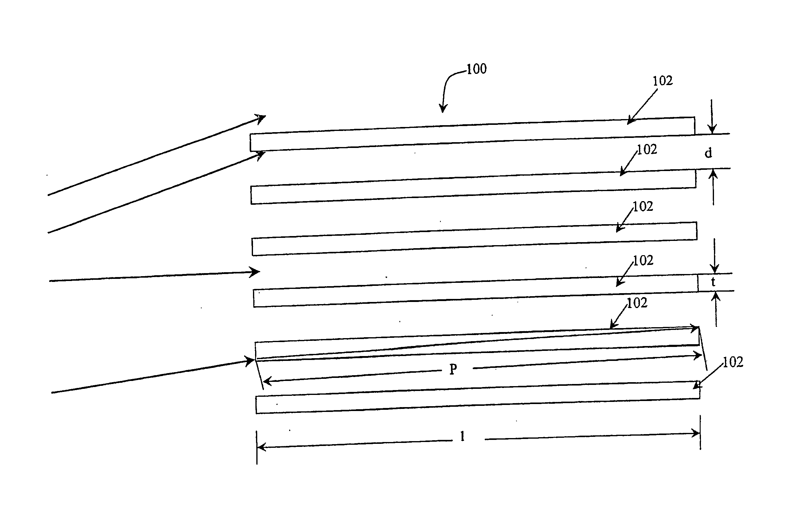
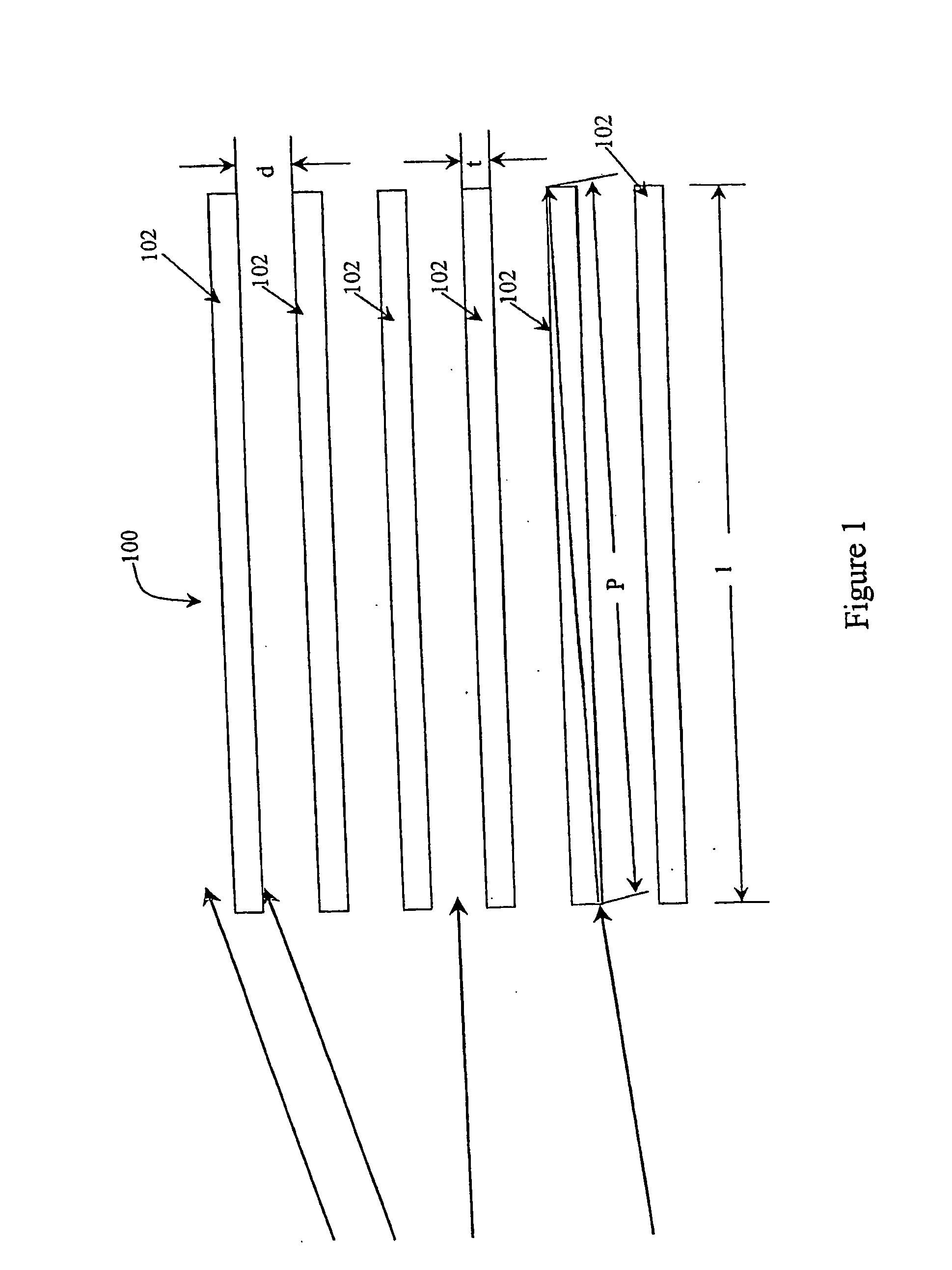
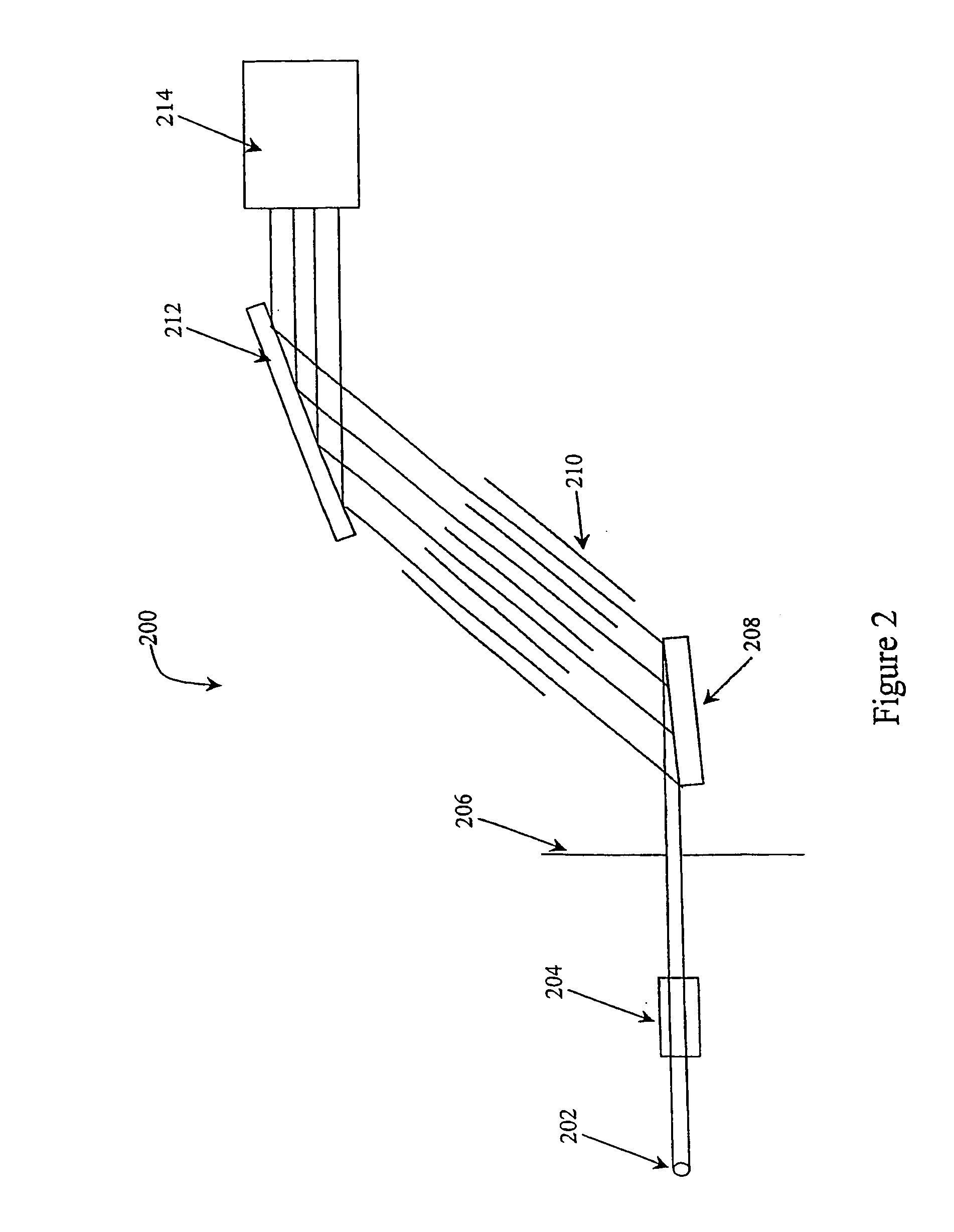
[0021] To facilitate an understanding of the principles that underlie the present invention, it will be described hereinafter with particular reference to embodiments thereof, and specific applications wherein it is used. It will be appreciated by those skilled in the art, however, that the practical applications of the invention are not limited to the particular embodiments described herein. Rather, the invention will find utility in a variety of different applications wherein a Soller slit X-ray collimator having a high transmission throughput efficiency and / or a low divergence associated therewith is desirable. The present invention provides commercial advantages for multiple applications, as the Soller slit device of the present invention provides a transmission efficiency that is much greater and a divergence angle that is much less than those associated with traditional high energy radiation or X-ray optics used in high energy radiation applications, such as X-ray diffractomet...


PUM

PropertyMeasurementUnit
densityaaaaaaaaaa
lengthaaaaaaaaaa
lengthaaaaaaaaaa

Abstract

A Soller slit device is provided for collimation of high energy radiation, such as X-ray or EUV radiation, and has a low angle of divergence (less than 0.1°) and a high transmission efficiency (60 to 80% or greater). The Soller slit is made up of multiple blades of low-density material, such as glass, mica, or the like, which are treated to reduce reflectivity. The Soller slit device of the invention advantageously provides an increased peak intensity and decreased peak width in diffraction patterns produced in high energy diffractometry applications, such as X-ray diffractometry.

Description

FIELD OF THE INVENTION [0001] The present invention relates to X-ray metrology. Specifically, the present invention relates to an absorption element used to control the divergence of a beam of X-rays. BACKGROUND OF THE INVENTION [0002] In recent years, technology involving high energy radiation, such as X-ray and extreme ultraviolet (EUV) radiation has increased. However, because of the very nature of this type of radiation, it is often difficult to control its divergence. One common optical element used for controlling the divergence of an X-ray beam is called a Soller slit. Soller slits generally comprise a set of parallel, or nearly parallel, plates or blades that limit the divergence of an X-ray beam by simple blocking or absorption of divergent rays, which are not allowed to pass through an open section of the array. [0003] Typically, Soller slits have been made of materials of high density to allow for absorption of divergent X-rays. It has been generally thought that material...

Claims


Application Information

Patent Timeline
Patent Type & Authority Applications(United States)
IPC IPC(8): G01N23/20G21K1/02
CPCG21K1/025
Inventor INNEMAN, ADOLFPINA, LADISLAVBOWEN, DAVID KEITH
Owner BEDE
Why Eureka
Try Eureka