Conductive antenna structure and method for making the same

a technology of conductive antennas and antenna structures, applied in the direction of resonant antennas, radiating element structural forms, printed circuit manufacturing, etc., can solve the problems of waste liquid treatment, unsuitable fast mass production methods, waste of materials, etc., and achieve the effect of reducing manufacturing costs, improving throughput efficiency, and having production flexibility

Inactive Publication Date: 2007-10-18
CHEN YUNG SHUN
View PDF11 Cites 5 Cited by
  • Summary
  • Abstract
  • Description
  • Claims
  • Application Information

AI Technical Summary

Benefits of technology

[0014] The primary objective of the invention is to provide a conductive antenna structure and method for making the same wherein the conductive antenna made by using the plastic film as a substrate and by the use of evaporating and rinsing methods has the advantages of effectively lowering the manufacturing cost, improving the throughput efficiency, and having production flexibility.
[0015] The secondary objective of the invention is to provide a conductive antenna structure and method for making the same, wherein the manufacturing method is pertinent in production automation of industrial management and is high in efficiency. Besides, the products produced by the manufacturing process of the invention are good in flexibility, and are light in weight, and thin, short, and small in dimension. What is more, the employed material conform the regulation of environmental protection.

Problems solved by technology

This kind of fabricating method is not appropriate for fast mass-production due to the tended high unit price since the material cost is relatively high and the fabricating process is rather complicated.
Besides, the waste liquids generated will do harm to the environment, and the waste liquid treatment will cost a lot.
Therefore, oftentimes it is very hard to consider together all of the factors such as process cost, throughput efficiency, and flexibility.
The price of the raw material and the cost of process of the conventional etching copper-foil substrate are very high.

Method used


Image

  • Conductive antenna structure and method for making the same
  • Conductive antenna structure and method for making the same
  • Conductive antenna structure and method for making the same

Examples


Embodiment Construction

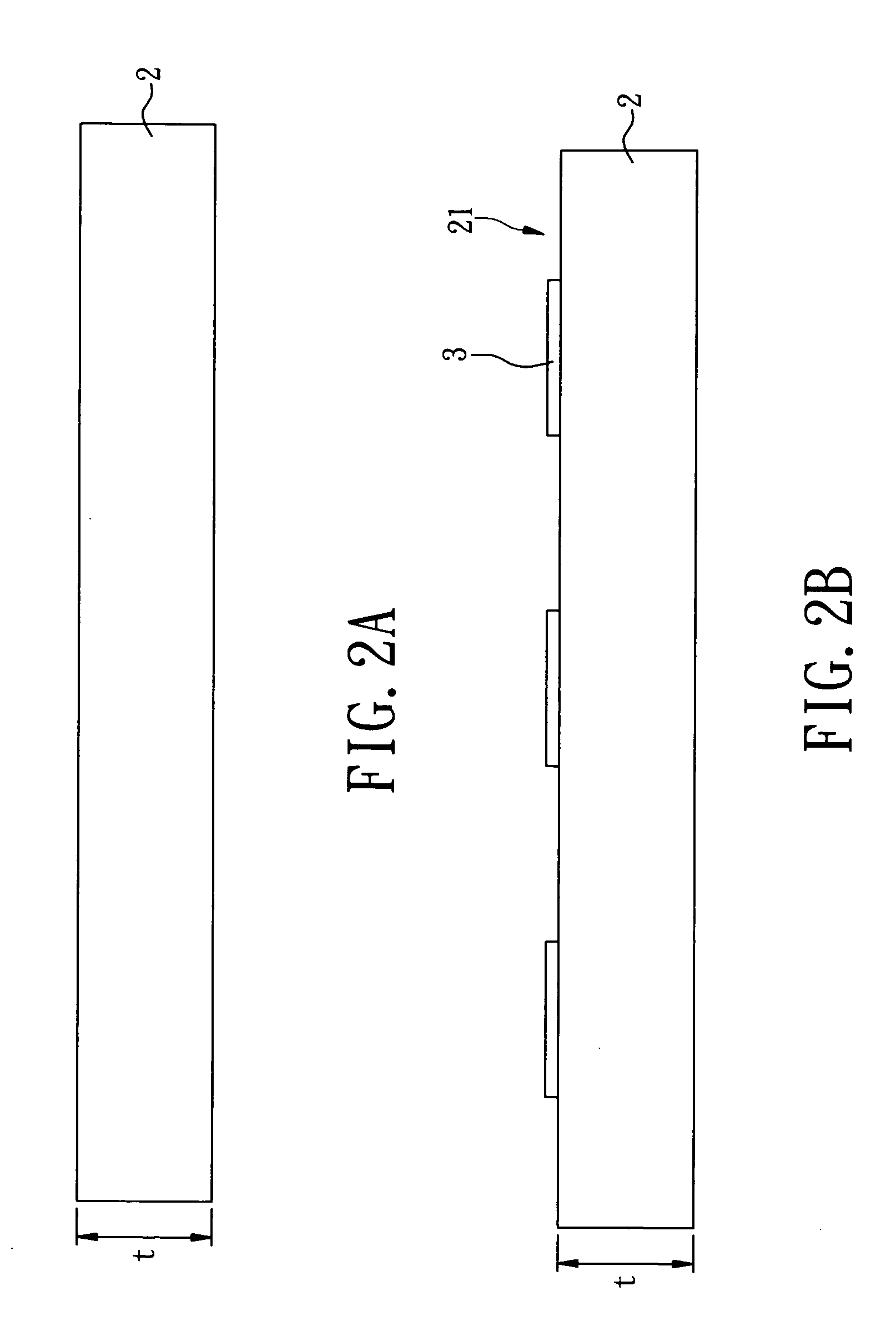
[0023]FIG. 2A through FIG. 2D are schematic side views showing the method for making the conductive antenna of the preferred embodiment of the invention. As shown in FIG. 2A, the method for making the conductive antenna of the invention provides a plastic film substrate (2) made of Polyethylene Terephthalate (PET) which is generated by the combination of terephthalic acid and ethylene alcohol. The PET plastic is adopted because it has the following characteristics: 1. High durability and transparency—good heat-resistance and heat-insulation and having high transparency; 2. Beneficial to environmental protection: PET is an environmental protection plastic material that can replace PVC (Polyvinyl Chloride) plastic which is harmful to the environment; 3. It can be recycled: PET plastic being a most valuable material in recycling can be recycled and reprocessed into manmade fiber or secondary processed plastic products; 4. It is light in weight, impact durable, and not apt to crack.

[00...


PUM


Abstract

A conductive antenna structure and method for making the same, wherein the method includes the following steps: (a) providing a plastic film substrate: (b) performing a rinsing coating material printing process to let the rinsing coating material position on the plastic film substrate and appear a predetermined antenna pattern; (c) performing an evaporating process for the plastic film substrate to provide a conductive layer thereon; (d) performing a rinsing process for the plastic film substrate to separate the rinsing coating material from the plastic film substrate and let the conductive layer position on the antenna pattern. Therefore, the conductive antenna structure made by the use of the above-mentioned method includes a plastic film substrate made of Polyethylene Terephthalate (PET) as well as a conductive antenna that is made of conductive material and is connected to the surface of the plastic film substrate, and has a predetermined first thickness.

Description

BACKGROUND OF THE INVENTION [0001] 1. Field of the Invention [0002] The invention relates to a conductive antenna structure and method for making the same, and more particularly, to a conductive antenna structure and method for making the same that makes use of a base material made of Polyethylene Terephthalate (PET) employed in wireless radio frequency antenna. [0003] 2. Description of the Prior Art [0004] The Radio Frequency Identification (RFID) being a system making use of wireless electromagnetic wave to transmit Identification data and the application thereof and being very widespread has the following merits: [0005] 1. Data can be updated: Unlike the conventional bar code that is unable to be updated after it is printed, RFID-TAG is capable of adding, modifying and erasing the stored data at unlimited number of times. [0006] 2. Data are easy to Identify: The conventional bar-code reader can identify only within closed distance and without any blocking objects to let the scann...

Claims


Application Information

Patent Timeline
Patent Type & Authority Applications(United States)
IPC IPC(8): H01Q1/38
CPCH05K1/0393H05K2203/097H05K3/048
Inventor CHEN, YUNG-SHUN
Owner CHEN YUNG SHUN
Why Eureka
Try Eureka