Reduction of banding and mottle in electrophotographic systems

a technology of electrophotography and banding, applied in the field of electrophotographic recording apparatus, can solve the problems of undesirable banding or mottle levels in images that have acceptable density on average, and achieve the effect of reducing mottle or banding

Inactive Publication Date: 2005-04-26
EASTMAN KODAK CO +1
View PDF12 Cites 22 Cited by
  • Summary
  • Abstract
  • Description
  • Claims
  • Application Information

AI Technical Summary

Problems solved by technology

However, images that have acceptable density on average can have undesirable levels of banding or mottle.
Banding is generally due to speed variations in image movement, often caused by gear noise, stepper motor frequencies, or scanner frequency variations.

Method used


Image

  • Reduction of banding and mottle in electrophotographic systems
  • Reduction of banding and mottle in electrophotographic systems
  • Reduction of banding and mottle in electrophotographic systems

Examples


Embodiment Construction

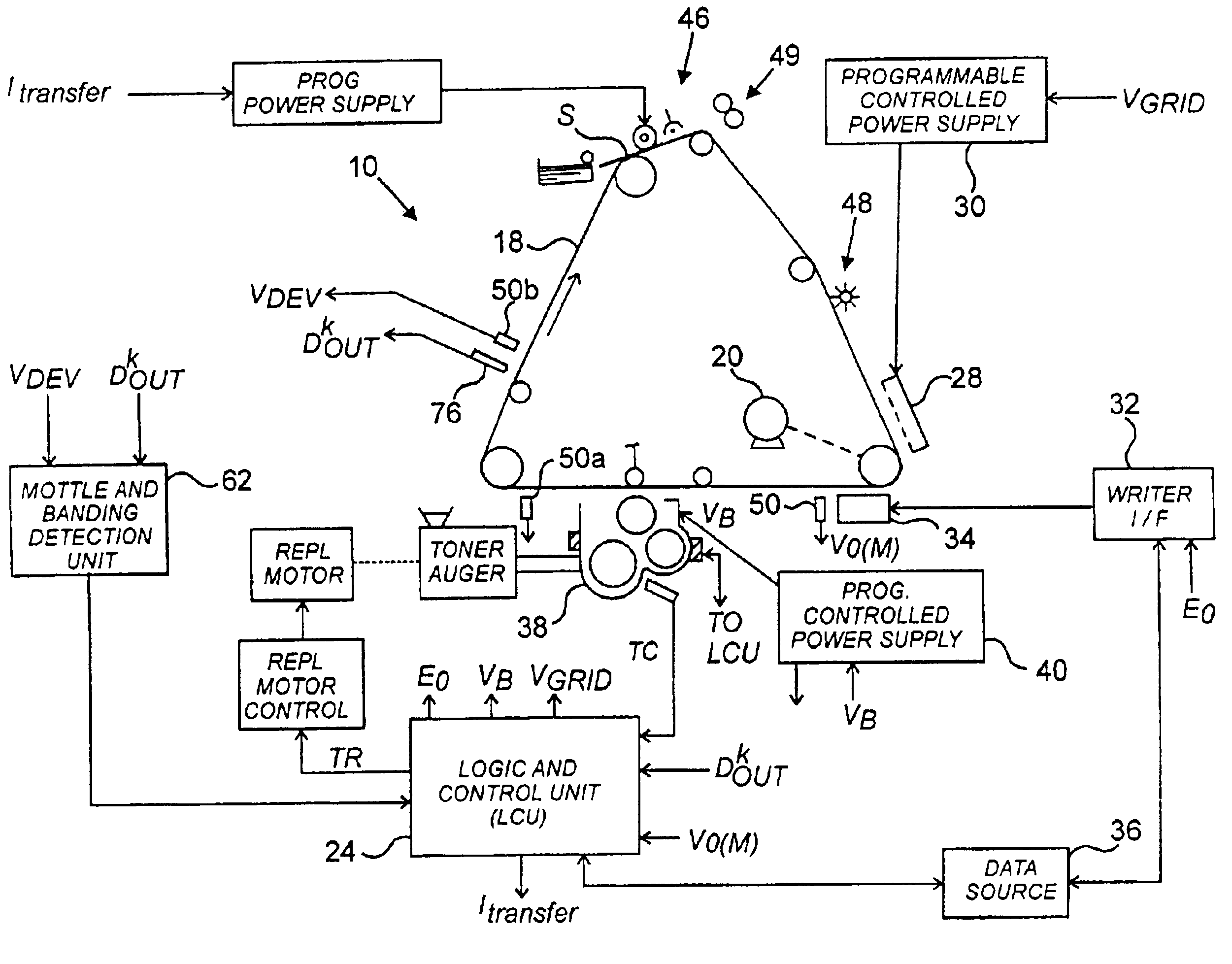
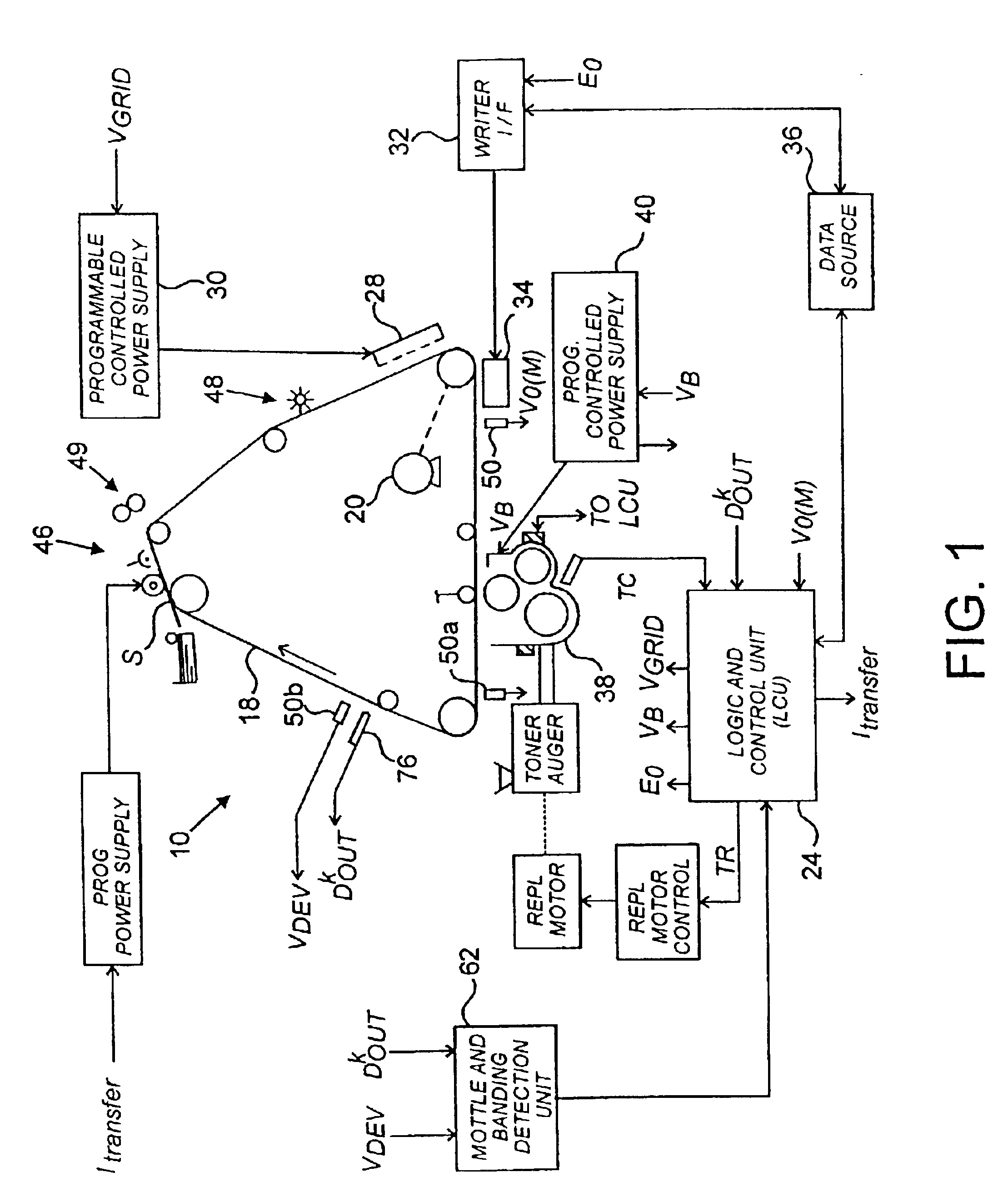
[0021]The machine 10 diagrammed in FIG. 1, an electrophotographic printer, is typical of devices containing the invention. In machine 10, a moving recording member such as photoconductive belt 18 is driven by a motor 20 past a series of work stations of the printer. A logic and control unit (LCU) 24 has a digital computer that operates a stored program for sequentially actuating the electrophotographic stations. The invention's mottle and banding detection unit 62 provides signal inputs to LCU 24 to direct changes to operating parameters for machine 10. Detection unit 62 is shown here as a separate component, to highlight the invention's structure and operation. Detection unit 62 may exist as a separate component or as an integrated subsystem of LCU 24.

[0022]In typical devices such as machine 10, charging station 28 sensitizes belt 18 by applying a uniform electrostatic charge of predetermined primary voltage V0 to the surface of the belt 18. The output of the charger 28 is regulate...


PUM


Abstract

A mechanism and process for detecting mottle or banding in a developed electrophotographic image. Within an electrophotographic reproduction apparatus 10, a photoconductor is used for receiving and developing a latent image. The photoconductor traverses a path that passes a charging station 28, an exposure station 34, a toning station 38, and a transfer station 46. Either a densitometer 76 for measuring the density of the developed image on the photoconductor, or an electrometer 50a or 50b for detecting the voltage of the image on the photoconductor, detects mottle or banding on the developed image. The densitometer 76 or electrometer 50a or 50b has an aperture small enough to detect mottle or banding with wavelengths perceptible by human eyes. A logic and control unit 24 averages the image density or voltage measurements, calculates the variations of the measurements about the average and the periodicities of the measurements, and if the variations or periodicities indicate mottle or banding is present, changes the operation of one or more stations to reduce mottle or banding.

Description

CROSS-REFERENCE TO RELATED APPLICATIONS[0001]This patent application claims the benefit of the priority date of Provisional patent application Ser. No. 60 / 302,457 filed Jul. 2, 2001.FIELD OF INVENTION[0002]This invention relates to electrophotographic recording apparatus such as that used in document copiers and printers, and more specifically to output quality control in an electrophotographic recording apparatus.Definitions[0003]The following terms well-known in the art are defined here:[0004]Iexp—Writer current used during exposure.[0005]Vexp—Writer voltage used during exposure.[0006]E0—Light produced by the print head.[0007]E—Actual exposure of photoconductor.[0008]V0—Primary voltage (relative to ground) on the photoconductor just after the charger. This is sometimes referred to as the “initial” voltage.[0009]VB—Development station electrode bias.[0010]Vgrid—A grid control signal that controls the transfer of initial charge to the photoconductor.Discussion of Prior Art[0011]Proc...

Claims


Application Information

Patent Timeline
Patent Type & Authority Patents(United States)
IPC IPC(8): G03G15/00
CPCG03G15/5041G03G15/5037G03G2215/00042G03G2215/00054
Inventor STELTER, ERIC C.FRIEDRICH, KENNETH P.GUTH, JOSEPH
Owner EASTMAN KODAK CO
Why Eureka
Try Eureka