Stator for an automotive alternator

a technology for automotive alternators and stator coils, which is applied in the direction of magnetic circuit rotating parts, magnetic body, and magnetic circuit shape/form/construction, etc., can solve the problems of insufficient suppression of surges in magnetic flux, inability to sufficiently suppress surges in generated voltage, and poor installation time and installation characteristics of stator coils in the stator core b>23/b>, so as to reduce the higher harmonic components of magnetomotive force, good stator coil installation

Inactive Publication Date: 2005-05-03
MITSUBISHI ELECTRIC CORP
View PDF44 Cites 9 Cited by
  • Summary
  • Abstract
  • Description
  • Claims
  • Application Information

AI Technical Summary

Benefits of technology

[0014]The present invention aims to solve the above problems with the conventional art and an object of the present invention is to provide a stator for an automotive alternator which has good stator coil installation characteristics, which further has a large effect on surges in magnetic flux and the magnetic attractive force between the stator and a rotor, and which can reduce higher harmonic components of magnetomotive force in the stator

Problems solved by technology

In a conventional automotive alternator constructed as above, since the stator core has 72 slots, which is a lot, there is a problem in that the insertion time and installation characteristics of the stator coils 23 in the stator core 22 are poor.
Nevertheless, eleventh (11th) and thirteenth (13th) higher harmonic components of magnetomotive force in the stator 8 are large, and when 11th or 13th higher harmonic components of magnetomotive force are present in the rotor 6 there are problems in that, surges in magnetic flux cannot be sufficiently suppressed due to interference by the harmonic components and fluctuation in the generated voltage cannot be sufficiently suppressed.

Method used


Image

  • Stator for an automotive alternator
  • Stator for an automotive alternator
  • Stator for an automotive alternator

Examples


embodiment 1

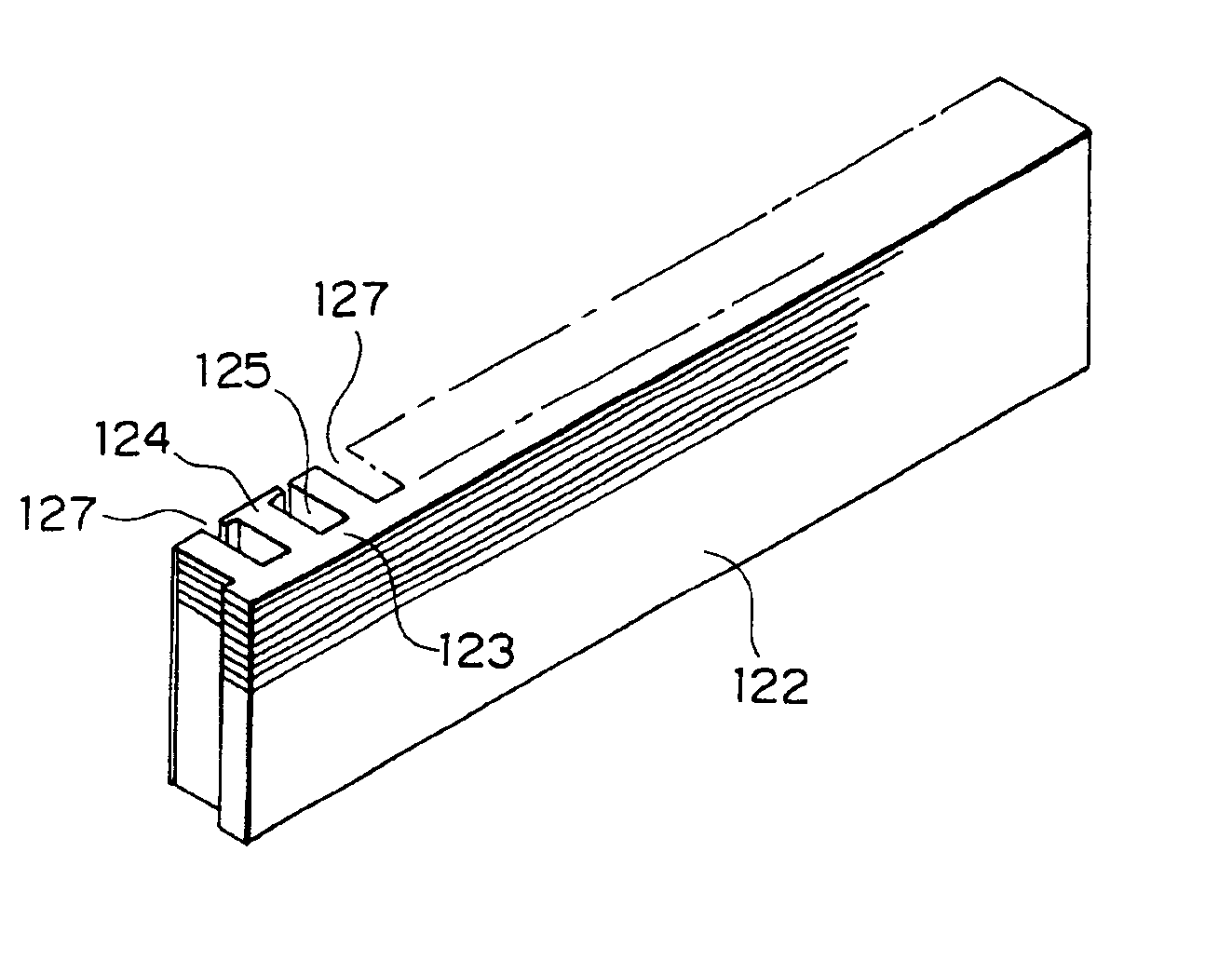
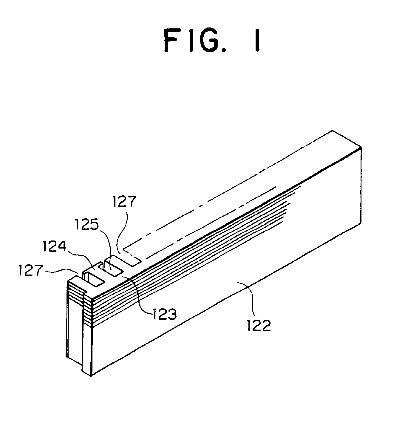
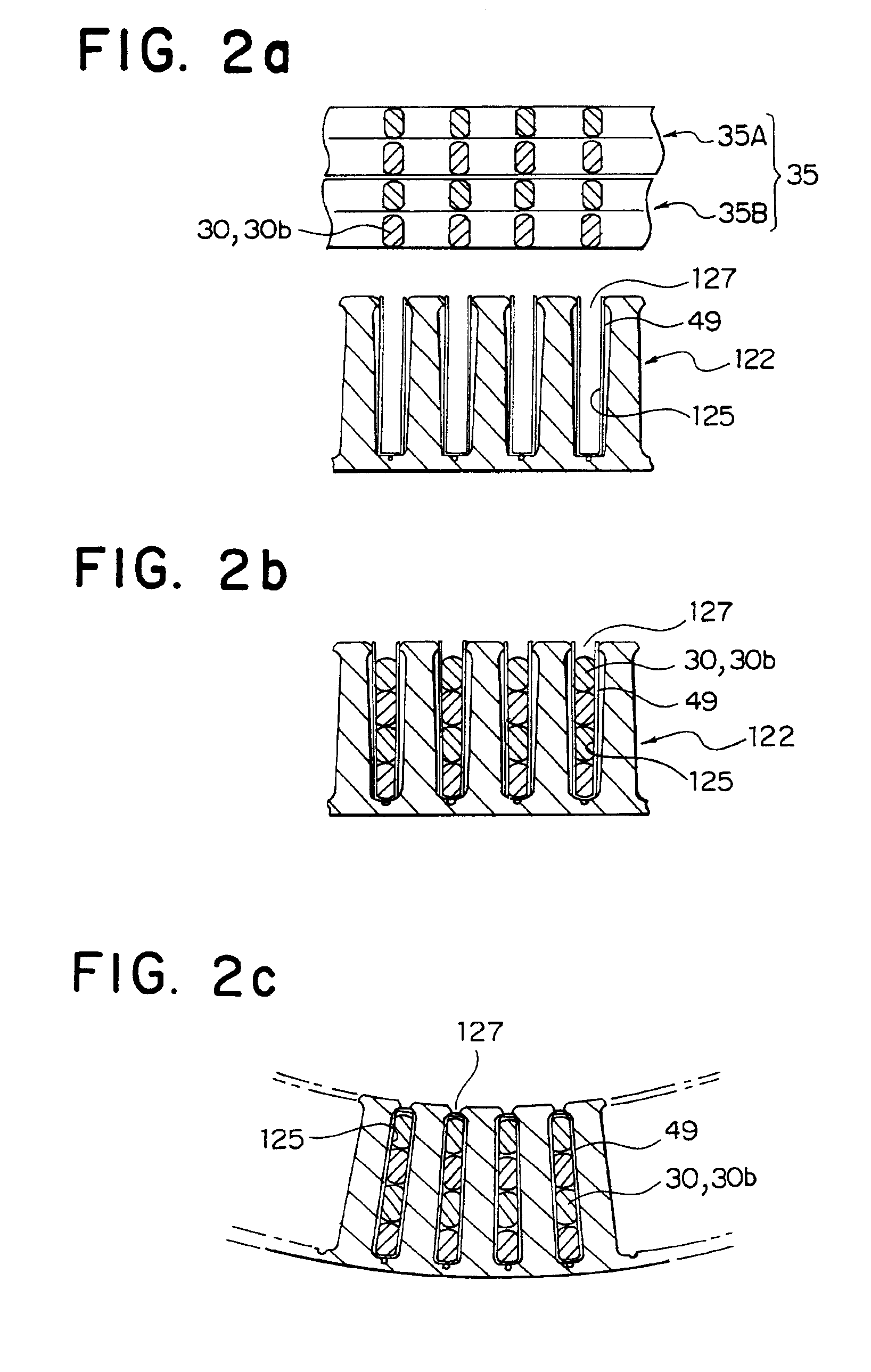
[0039]FIG. 1 is a perspective view for explaining a former winding structure of a stator core applied to the stator for a automotive alternator according to the present invention. FIG. 2 is a process sectional view for explaining the manufacturing process of a stator core. FIG. 3 is a perspective view for explaining the manufacturing process of a stator core. FIG. 4 is a front view of a stator core. FIG. 5 is a partial enlarged view of a stator core. FIG. 6 is a circuit diagram of the automotive alternator according to the present invention.

[0040]As shown in FIG. 1, a stator core 122 according to the present invention is formed in a rectangular shape by laminating a predetermined number of sheets of a SPCC material which are sheet-shaped magnetic members punched in a predetermined shape. A total number of seventy-two (72) teeth 124, which is the same as in the related art, are formed at one side of a yoke 123. Trapezoid-shaped slots 125 are formed between adjacent teeth 124.

[0041]As...

embodiment 2

[0050]FIG. 7 is an enlarged view of an essential portion of a stator core showing another example of the stator for a automotive alternator according to the present invention. In a stator core 222 according to the present invention, adjacent teeth 224 are formed with uneven widths. Slots 225 have approximately the same widths, and an interval in the circumferential direction between the center of air gaps of adjacent slot opening portions 227 is an uneven, repeated interval of 24 degrees and 36 degrees.

[0051]Accordingly, projections 224a extending in a circumferential direction formed in slot opening portions 227 may be formed in the same shape. Consequently, similar effects may be obtained without forming the long and thin projections and short projections provided in Embodiment 1.

[0052]Furthermore, in the present embodiment, a wide tooth 224 is divided in a circumferential direction by substantially orthogonal surfaces 224b. These surfaces 224b serve as contact surfaces when conne...


PUM

PropertyMeasurementUnit
electrical angleaaaaaaaaaa

Abstract

A stator for an automotive alternator is provided with good installation characteristics for stator coils and which can lower noise. The stator includes a stator core in which a plurality of slots are formed at an inner circumference thereof and stator coils which are fitted into the slots. A rotor is provided inside the stator and includes a rotor coil, and a pole core for housing the rotor coil. Two slots are provided for each set of stator coils, each phase and each magnetic pole and the total number of slots is seventy-two or more. The stator core formed by laminating a plurality of sheet-shaped magnetic members. The stator coils are disposed in the slots, and the stator core is rounded such that the stator coils become the inner side thereof and both end surfaces thereof are contacted to connect the stator core in an annular shape.

Description

[0001]This is a Divisional of application Ser. No. 09 / 625,993 filed Jul. 26, 2001, the disclosure of which is incorporated herein by reference.BACKGROUND OF THE INVENTION[0002]1. Field of the Invention[0003]The present invention relates to an alternator driven by an internal combustion engine, and in particular, relates to a stator for an automotive alternator mounted in a vehicle such as a passenger car or truck.[0004]2. Description of the Related Art[0005]FIG. 8 is a sectional side elevation of a conventional automotive alternator. FIG. 9 is a front view of a stator core applied to a stator of a conventional automotive alternator. FIG. 10 is a circuit diagram of a conventional automotive alternator. The conventional automotive alternator shown in the figures includes, a case 3 constructed from an aluminum front bracket 1 and rear bracket 2, a shaft 5 with a pulley 4 fixed on one end thereof provided so as to be capable of rotating inside the case 3, a Lundell rotor 6 fixed to the ...

Claims


Application Information

Patent Timeline
Patent Type & Authority Patents(United States)
IPC IPC(8): H02K3/12H02K3/34H02K9/06H02K3/50H02K1/16H02K3/28H02K3/32H02K9/04H02K15/00H02K15/02H02K15/06H02K15/04H02K19/22
CPCH02K1/16H02K3/12H02K3/28H02K3/345H02K9/06H02K15/024H02K15/0435H02K15/066H02K3/50H02K1/165Y10T29/49009H02K2203/09Y10S29/048Y10T29/49012Y10T29/49073H02K15/0478Y10T83/0476Y10T83/0505Y10T83/051Y10T83/0577H02K15/02
Inventor HIGASHINO, KYOKOADACHI, KATSUMI
Owner MITSUBISHI ELECTRIC CORP
Why Eureka
Try Eureka