Decorative bench barrier

a bench and decorative technology, applied in the field of decorative benches, can solve the problems of occupying a considerable amount of space and a large amount of space, and achieve the effect of facilitating transportation and placement of the bench barrier and enhancing its aesthetic utility

Inactive Publication Date: 2005-05-03
MAYER RODIS NANCY J
View PDF17 Cites 12 Cited by
  • Summary
  • Abstract
  • Description
  • Claims
  • Application Information

AI Technical Summary

Benefits of technology

[0006]It is an object of this invention to provide a decorative bench barrier that can serve the dual purposes of providing seating for people as well as security to people, buildings, parks, etc.
[0007]According to the invention, the bench barrier is manufactured using best practices for precast concrete. The bench barrier will be created from one or more elements, each of which are integrally formed from concrete, and each of which has a base, a back section, and seating portions on either side of the back section. The elements may take a variety of shapes. One preferred shape will have a straight longitudinal axis. Another preferred shape will be in the form of an arc. The arc shaped elements (or “radial” elements) may have a radius of curvature of 5° to 180°, but is most preferably approximately 45° or 90°. A number of arc shaped elements may be joined end-to-end to make a circle which could, for example, accommodate a planter, tree, light post or street sign in a central region. In addition, arc shaped elements may be configured end-to-end in an alternating pattern to create serpentine seating / barrier configuration which may be more aesthetically pleasing in park like settings. Straight sections could provide protected seating along roadways, and may be interconnected with arc shaped sections to create U-shaped and or box shaped designs. The bench barrier elements can be colored or treated with a decorative surface coating to enhance their aesthetic utility. Lifting pockets and / or lifting devices can be integrally formed in the base section of the bench barrier to facilitate transporting and placement of the bench barrier.

Problems solved by technology

While these devices are functional for security, they have significant aesthetic drawbacks.
In addition, they tend to use a considerable amount of space without providing additional functionality.

Method used


Image

  • Decorative bench barrier
  • Decorative bench barrier
  • Decorative bench barrier

Examples


Embodiment Construction

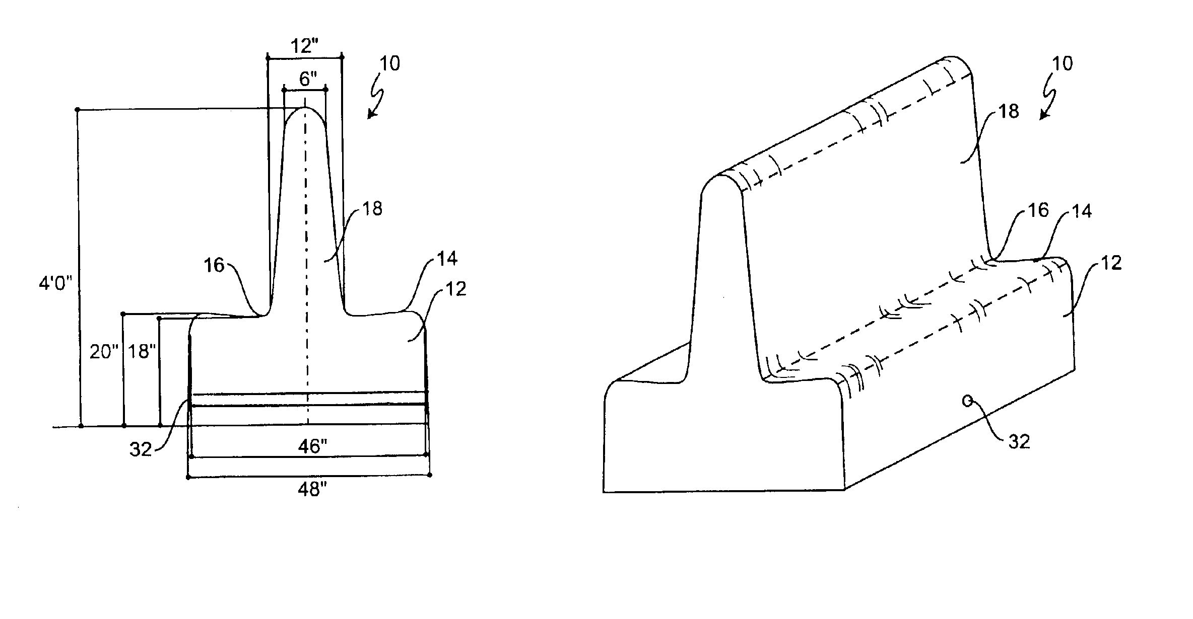
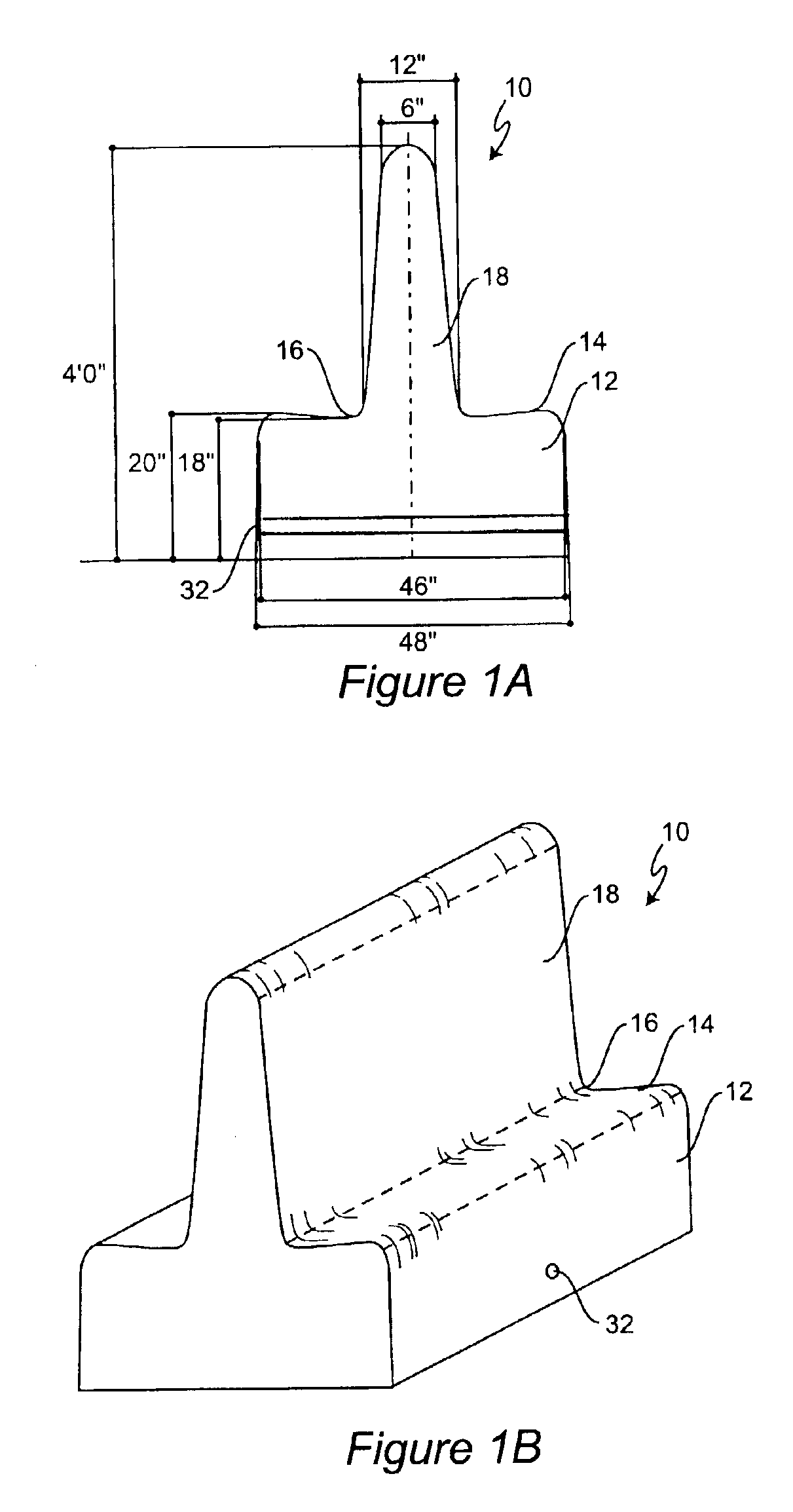
[0018]Referring now to FIGS. 1A and 1B. there is shown cross-sectional and isometric views, respectively, of a decorative bench barrier 10 according to the invention. The decorative bench barrier 10 includes a base 12, seating sections 14 and 16, and a back section 18. The back section 18 is preferably two sided and is less than 50% of the width of the base 10. Most preferably, the base is approximately four times the width of the back section.

[0019]In the preferred embodiment, and for exemplary purposes only, the width of the base will be 48″ and will be slightly angled inward towards the vertical height dimension to 46″. The back section 18 will be centrally located on top of the base 12, and will have a 12″ cross-section at the bottom and incline inward to a 6″ cross-section at the top. The height of the decorative bench barrier is 48″, and the seat sections 14 and 16 will be located 20″ above the ground and will incline downward to 18″ as they approach the back section 18. It sh...


PUM


Abstract

A decorative bench barrier serves the function of providing security for buildings, memorials, and people, while at the same time providing aesthetically pleasing seating suitable for long term use on city streets, in parks, and in other areas. The decorative bench barrier is constructed from one or more reinforced precast concrete elements which include a wide base, a central seating region, and a top back rest. The reinforced precast concrete elements are made in straight sections and radius sections. The radius sections are preferably either 45° or 90°. The sections are interconnectable so that a circular, square, serpentine or other suitable configuration for the bench barrier can be assembled on site.

Description

[0001]This application claims the benefit of provisional application No. 60 / 377,262 filed May 1, 2002.BACKGROUND OF THE INVENTION[0002]1. Field of the Invention[0003]The invention generally relates to a barriers used for security applications such as, for example, in streets and in front of buildings.[0004]2. Description of the Related Art[0005]A wide variety of barrier systems have been used in roadway applications for the purposes of delineating driving lines, blocking off areas, and in other ways focused on the control of traffic. A common barrier system is a curved precast concrete device sometimes referred to as a “Jersey wall”. To satisfy current security demands, these same traffic oriented devices are now being used in the front of government buildings, along the edges of sidewalks, and in parks. While these devices are functional for security, they have significant aesthetic drawbacks. In addition, they tend to use a considerable amount of space without providing additional...

Claims


Application Information

Patent Timeline
Patent Type & Authority Patents(United States)
IPC IPC(8): E01F15/00E01F15/14E01F13/12E01F15/08
CPCE01F15/083E01F13/12
Inventor MAYER RODIS, NANCY J.
Owner MAYER RODIS NANCY J
Why Eureka
Try Eureka