Cooling system for nozzle segment platform edges

a technology of cooling system and nozzle segment, which is applied in the direction of machines/engines, stators, liquid fuel engines, etc., can solve the problems of affecting the cooling effect of the nozzle segment,

Active Publication Date: 2005-05-03
GENERAL ELECTRIC CO
View PDF7 Cites 60 Cited by
  • Summary
  • Abstract
  • Description
  • Claims
  • Application Information

AI Technical Summary

Benefits of technology

[0006]The outlet passages and passageways from each plenum are located such that each inlet passage does not have direct line-of-sight to the outlet passages and passageways. As a consequence, the cooling medium impinges on the walls of each plenum and provides additional internal convective cooling to the edges of the platform. Moreover, the cooling medium supply passages provide a substantially uniform pressure and flow of coolant along the length of the plenum, affording a continuous rather than discrete cooling effect. As a consequence of this arrangement, the edges of the platforms are cooled by (i) both conduction and convection due to the proximity of the plenum to the edge being cooled; (ii) cooling medium flowing through the outlet passages passing under the edge and into the intersegment gap through the outlet openings; (iii) impingement of the supplied cooling medium inside the plenum due to the lack of direct line-of-sight flow from the inlets to the outlets; and (iv) film cooling.

Problems solved by technology

Film cooling from an adjacent nozzle to cool the platform edge, however, causes a debiting of the cooling effectiveness when the cooling film crosses the nozzle intersegment gap.
When long holes running from an impingement cavity are utilized, the convective cooling of the edge by the holes is discrete rather than continuous and, therefore, less efficient.
Perfect alignment of the adjoining edges of the nozzle segments, however, is difficult to achieve and maintain as a result of manufacturing and thermomechanical problems.
A boundary layer trip at the adjoining edges of the platforms results in a spike in heat transfer near the edge of the platform and also results in a debit to the cooling effectiveness of any film cooling medium that crosses the gap.
Thus, the edges of nozzles segment platforms which extend generally parallel to the turbine axis are subject to severe thermal distress due to boundary layer trip.

Method used


Image

  • Cooling system for nozzle segment platform edges
  • Cooling system for nozzle segment platform edges
  • Cooling system for nozzle segment platform edges

Examples


Embodiment Construction

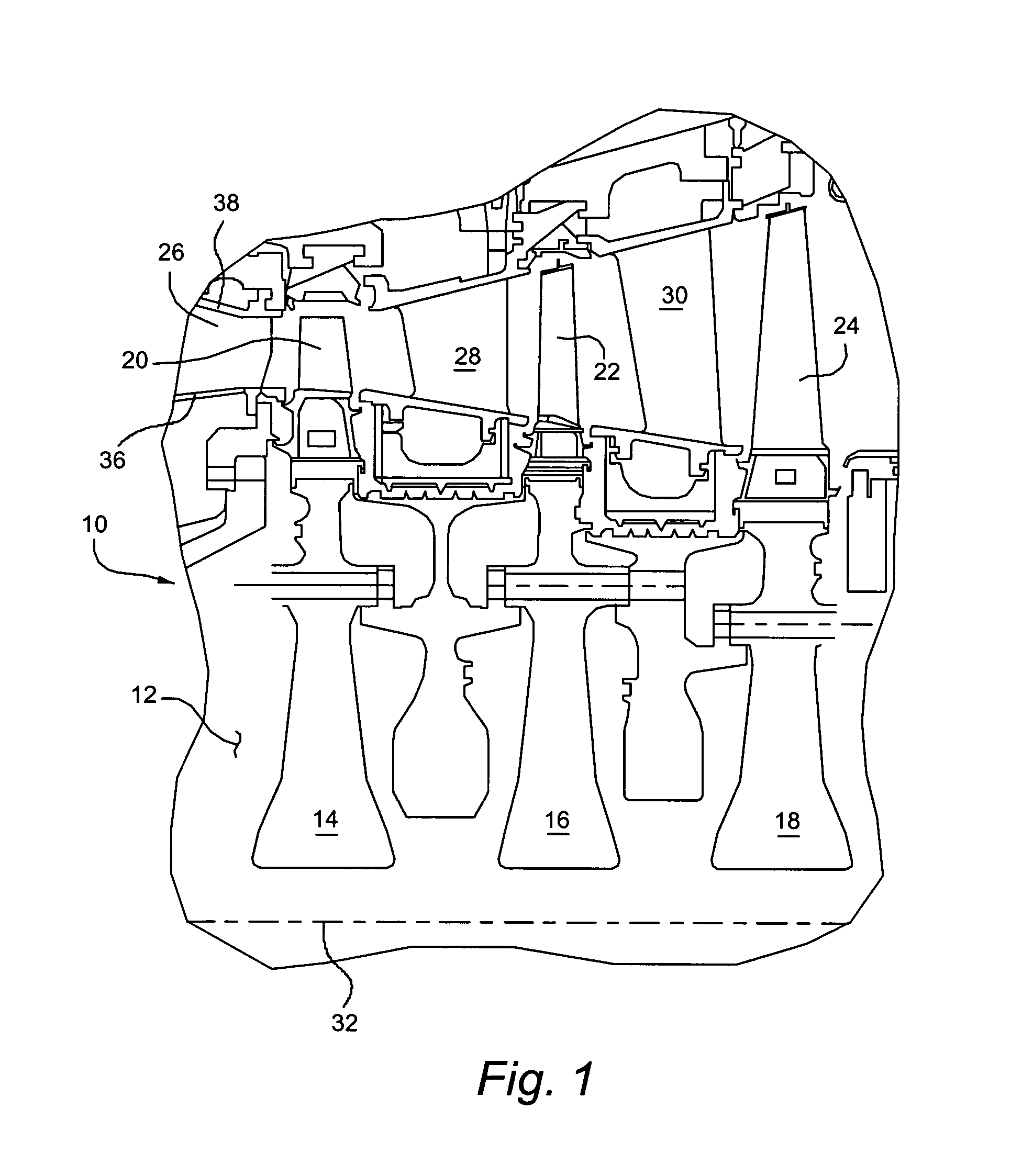
[0016]Referring now to the drawings, particularly to FIG. 1, there is illustrated a multi-stage turbine section, generally designated 10, including a rotor 12 having rotor wheels 14, 16 and 18. The rotor wheels 14, 16 and 18 mount buckets 20, 22 and 24, respectively, in the hot gas path of the turbine. The first, second and third nozzle stages are likewise illustrated and represented by the nozzle vanes 26, 28 and 30, respectively. It will be appreciated that the nozzle vanes 26, 28 and 30 turn and accelerate the hot gases to rotate the buckets and rotor about the axis 32 of the turbine.

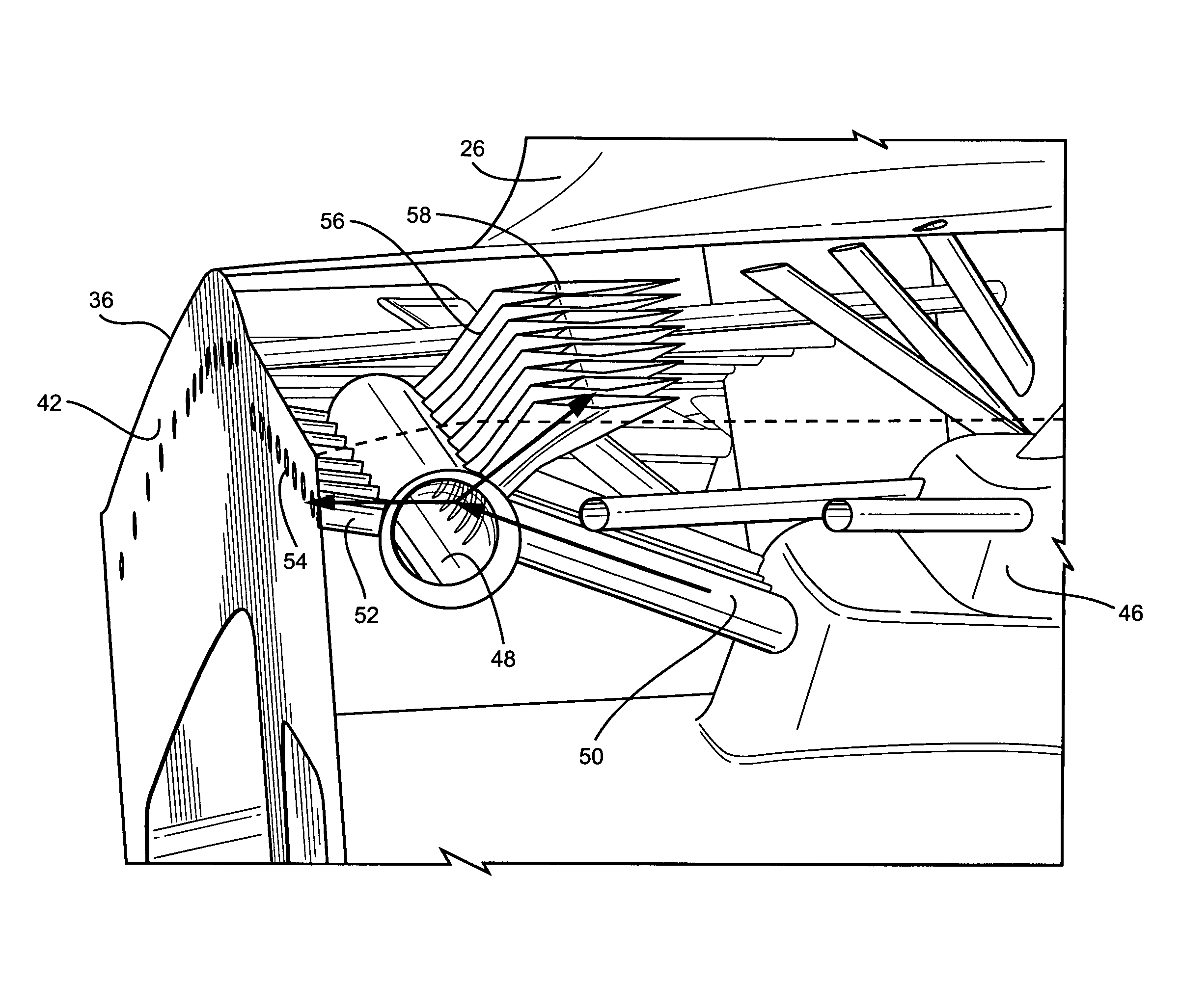
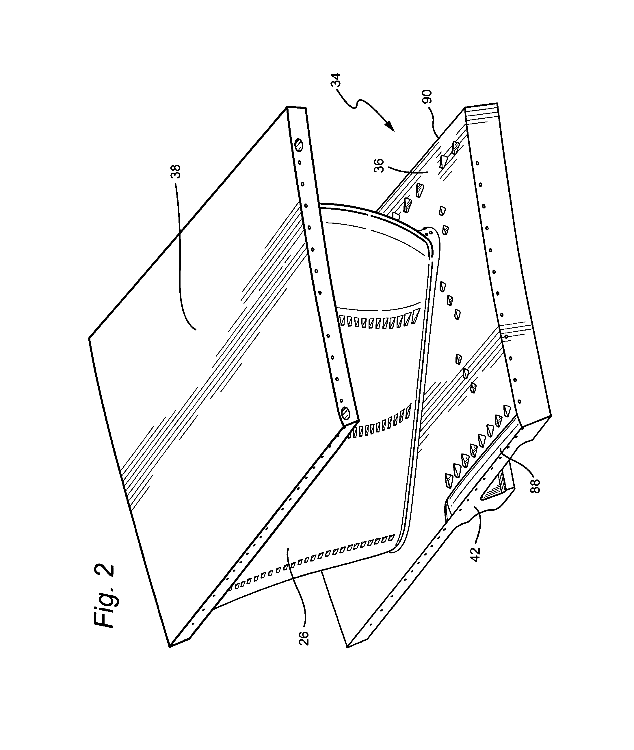
[0017]Referring to FIG. 2, the first stage nozzles are formed of a plurality of nozzle segments 34, each having an inner platform 36 and an outer platform 38 with at least one nozzle vane 26 extending between the inner and outer platforms. It will be appreciated that the nozzle segments 34 are disposed in an annular array about the axis of the turbine with the opposite edges of each of the inner and ...


PUM


Abstract

The cooling system for the nozzle edges includes a chamber containing a cooling medium. First and second elongated plenums are disposed along opposite side edges of each platform. Inlet passages communicate cooling medium from the chamber into each plenum. Outlet passages from each plenum terminate in outlet holes in the side edges of the platform to cool the gap between adjacent nozzle segments. Passageways communicate with each plenum and terminate in film cooling holes to film cool platform surfaces. In each plenum, the inlet passages are not in direct line-of-sight flow communication with the outlet passages and passageways.

Description

BACKGROUND OF THE INVENTION[0001]The present invention relates generally to a cooling system for the nozzle segments of a gas turbine and particularly relates to a cooling system for cooling the adjoining edges of inner and outer platforms of adjacent nozzle segments arranged in an annular array about the axis of the turbine.[0002]In gas turbines, annular arrays of nozzles are disposed in the hot gas path for turning and accelerating the gas flow for optimum performance of the buckets. In the first stage of a turbine, for example, there are a plurality of circumferentially spaced nozzle vanes which extend generally radially between inner and outer annular bands which serve to confine the gas flow to an annular configuration as the gas flows through the multiple stages of the turbine. A plurality of circumferentially spaced buckets mounted on the turbine rotor lie axially downstream of the annular array of nozzles and form a turbine stage with the nozzles. The nozzles, for example, o...

Claims


Application Information

Patent Timeline
Patent Type & Authority Patents(United States)
IPC IPC(8): F01D25/12F01D25/08F01D5/14F01D5/18F01D9/02F02C7/14F02C7/18
CPCF01D5/147F01D5/186F01D25/12F05D2260/202F05D2240/81F01D9/02F02C7/14
Inventor PHILLIPS, JAMES STEWARTMCGRATH, EDWARD LEEMEYER, ROBERT CARLBLOW, GERALD KENTMORROW, JENNIFER ANN
Owner GENERAL ELECTRIC CO
Why Eureka
Try Eureka