Method and apparatus for extruding polymers employing microwave energy

Inactive Publication Date: 2003-10-02
BOSTON SCI SCIMED INC
View PDF99 Cites 73 Cited by
  • Summary
  • Abstract
  • Description
  • Claims
  • Application Information

AI Technical Summary

Benefits of technology

0015] In accordance with another aspect of the invention, new polymer disks of varying properties are added in a continuous fashion without interrupting the forces pushing on the disk stack to achieve a continuous feeding process for the microwa

Problems solved by technology

One problem associated with such a process is that heating of the parison is less than optimal.
Moreover, the substantial time it takes to heat the parison in the central section having the widest distance between the mold and the parison, in comparison to the narrow space at both ends, lends itself toward a substantial heat flow axially along the parison at these end sections, which itself tends to heat portions of the polymeric material at which balloon deformation is not desired.
One problem stemming from such a system is that temperature control or distribution across the entire polymeric tube is difficult.
However, it will be clear that this material is obstructing the free expansion of the parison inside the mold.
Moreover, with such conventional systems, it is not possible to heat different axial sections of the polymeric tube to different temperatures.
Although a section of the mold can be kept above the fluid bath, and thus have the effect of producing a cooler section in the mold, due to the slow heating process a sharp temperature transition is not possible.
It is also not possible to set the metal mold to a different temperature than that to which the polymeri

Method used


Image

  • Method and apparatus for extruding polymers employing microwave energy
  • Method and apparatus for extruding polymers employing microwave energy
  • Method and apparatus for extruding polymers employing microwave energy

Examples


Embodiment Construction

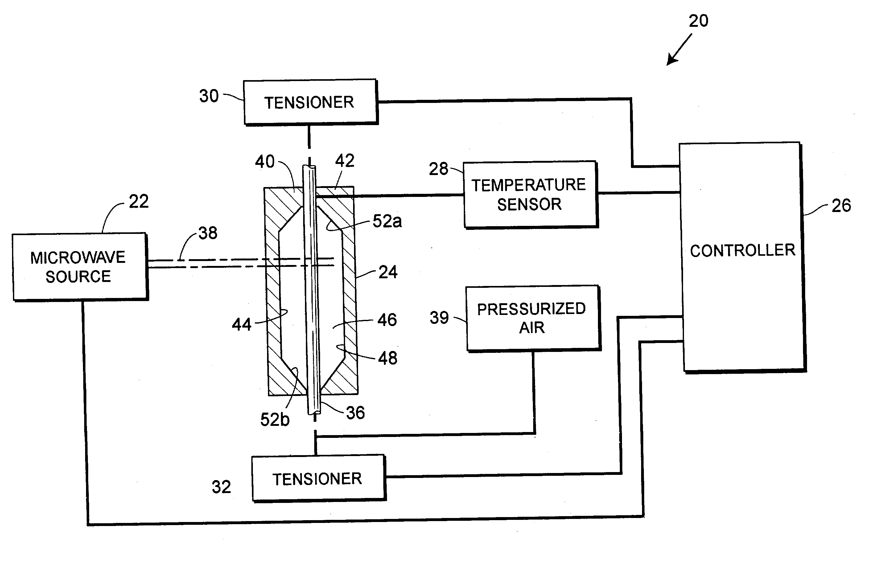
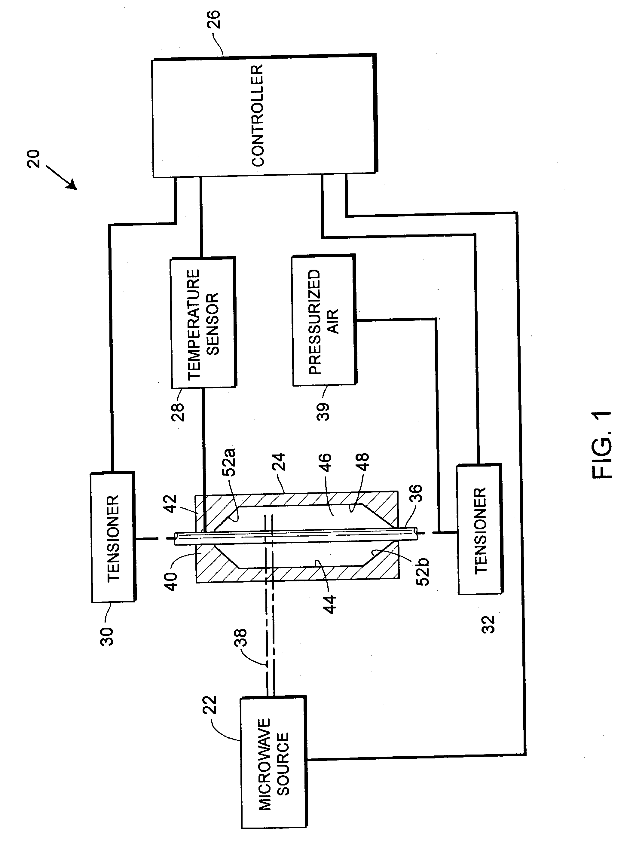
[0053] Referring now to the drawings, wherein like reference numerals indicate corresponding elements, and with specific reference to FIG. 1, a balloon catheter molding apparatus, constructed in accordance with the teachings of the disclosure, is generally referred to by reference numeral 20. As described herein, the apparatus 20 may be advantageously employed for the manufacture of balloon catheters and angioplasty balloons, but can be employed in conjunction with many other types of polymeric devices including, but not limited to, other medical devices or components of medical devices, such as contact lenses, graft material, hub mainfolds and the like.

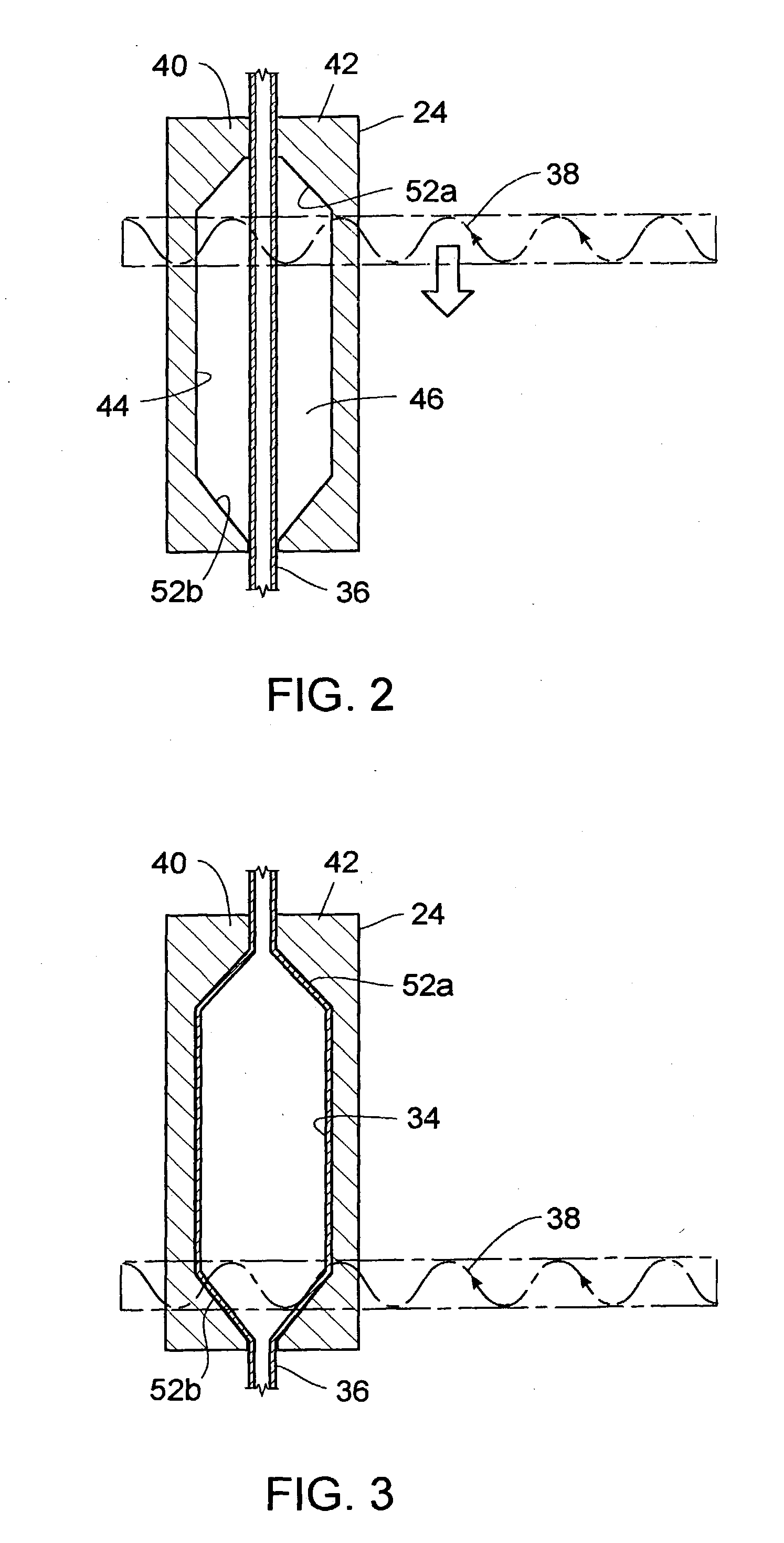
[0054] Referring again to FIG. 1, the system 20 may include a source of microwave energy 22, a mold 24, a controller or processor 26, a temperature sensor 28 and first and second tensioners 30, 32. Employing such elements, the apparatus 20 can form a balloon 34 (see FIG. 3) from a workpiece or parison 36. More specifically, the paris...


PUM

PropertyMeasurementUnit
Frequencyaaaaaaaaaa
Frequencyaaaaaaaaaa
Frequencyaaaaaaaaaa

Abstract

An apparatus and method for molding balloon catheters is disclosed. The balloon may be molded by providing a polymeric tube within a mold having an interior cavity in the shape of the desired balloon. Microwave energy, which may be generated by a gyrotron, may then be directed toward the mold, to heat the polymeric material without heating the mold. Once heated, pressurized fluid may be injected into the tube to blow the polymeric material against the interior cavity whereupon the material can cool to form the balloon or can be further heatset by additional microwave energy and be cooled to form the balloon. In accordance with one embodiment, microwave energy can also be used without a mold to form a medical device. A polymer extrusion apparatus is disclosed utilizing a microwave energy for heating polymer feedstock material within the extruder tip and die unit just prior to formation of the extrudate product. A cooling bath mechanism, which in one embodiment can also include a cooling tube member having a cooling medium forced therethrough, is also disclosed. An apparatus for preparing polymer disk members, to use as the polymer feedstock material for the microwave extrusion apparatus, is also disclosed. Apparatus for interconnecting and rotating the polymer disk members, the die tip, or the die, or any combination thereof, for creating angularity characteristics in the polymer extrudate, is also disclosed.

Description

[0001] This application is a continuation-in-part of U.S. patent application Ser. No. 10 / 212,926, filed on Aug. 6, 2002, which in turn is a continuation-in-part of U.S. patent application Ser. No. 10 / 109,220, filed on Mar. 28, 2002.FIELD OF THE DISCLOSURE[0002] The disclosure generally relates to extruded medical devices and, more particularly, relates to methods of manufacturing extruded medical devices, including with use of microwave energy, and for use in the field of angiography.BACKGROUND OF THE DISCLOSURE[0003] Angioplasty is an effective medical procedure performed to expand constricted sections of blood vessels. In such a procedure, an angioplasty balloon or balloon catheter is navigated to the site of the constriction. The balloon is inflated after reaching the site, by way of fluid pressure injected into the balloon, to thereby expand its dimension. The expansion of the balloon exerts pressure on the vessel walls to thereby widen the vessel and alleviate constriction to b...

Claims


Application Information

Patent Timeline
IPC IPC(8): A61F2/958A61M25/00A61M25/16B29B13/02B29C35/08B29C45/14B29C48/09B29C48/10B29C48/13B29C48/14B29C48/33B29C48/86B29C49/00B29C49/02B29C49/64B29C49/78B29K27/18B29K67/00B29K73/00B29K77/00B29K79/00B29L22/00H05B6/80
CPCA61M25/1027B29C2793/009A61M25/1034A61M25/1036B29B13/024B29C33/06B29C35/0805B29C45/14655B29C47/0023B29C47/0071B29C47/86B29C47/862B29C47/903B29C47/907B29C49/0042B29C49/64B29C49/66B29C49/78B29C49/783B29C2035/0855B29C2049/0089B29K2105/258B29L2022/022B29L2031/7542H05B6/80A61M25/1029B29C48/865B29C48/09B29C48/10B29C48/13B29C48/14B29C48/86B29C48/913B29C48/9135B29C48/919B29C48/903B29C48/907B29C2949/08B29C2049/7861B29C2049/78675B29C2049/78805
Inventor WEBER, JANSCHEWE, SCOTT
Owner BOSTON SCI SCIMED INC
Why Eureka
Try Eureka