In solid-state lasers (SSL),
optical pumping generates a large amount of heat within a laser medium and increases its temperature.
This causes a gradient in the index of
refraction, mechanical stresses,
depolarization, detuning, and other effects, with likely consequences of degraded beam quality, reduced laser power, and possibly a fracture of the SSL medium.
Such effects present a major challenge to scaling of SSLs to high-average power (HAP).
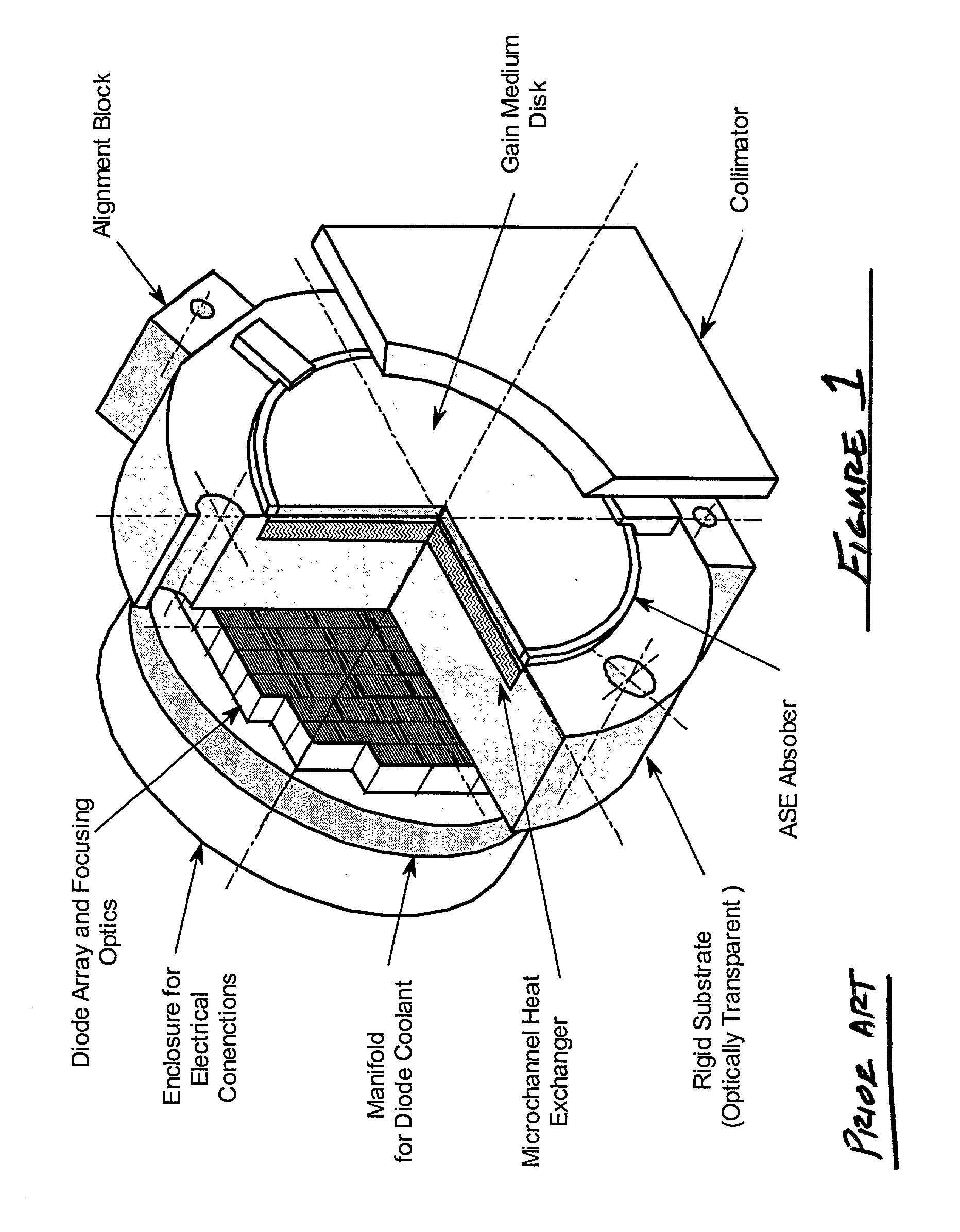
It has been long recognized that optical distortions caused by transverse temperature gradients (i.e., perpendicular to laser beam axis) degrade beam quality.
However, this device is not suitable for operation at HAP because of poor heat removal and resulting thermo-mechanical
distortion of the edge-suspended disk.
Previous attempts to mitigate these problems and increase the average
power output of an AMA were met with encouraging but limited results.
However, in many cases of interest it is impractical (or undesirable) to make the necessary increase in disk thickness or lasant
doping level.
For example,
doping a
yttrium-aluminum garnet (YAG)
crystal with
neodymium (Nd.sup.3+) ions beyond about 1.5% of atomic concentration is known to reduce the
fluorescence time, broaden the line-width, and excessively stress the
crystal due to a mismatch in size between the Nd atoms and
yttrium atoms (the latter being replaced in
crystal lattice).
Increasing the disk thickness is often undesirable as it also increases thermal impedance and leads to higher thermal stresses.
These considerations limit design parameters of face-pumped AMA to a relatively narrow regime.
Face pumping is also impractical in conjunction with
ytterbium (Yb.sup.3+) lasant ions, which require very high pump intensities to overcome re-absorption of laser radiation by the ground energy state.
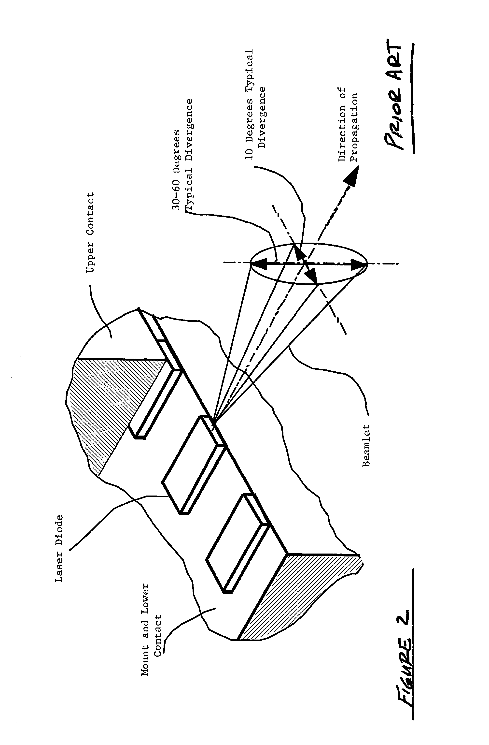
High
divergence in the
fast axis makes it more challenging to harness the emitted power of
diode arrays for use in many applications of practical interest.
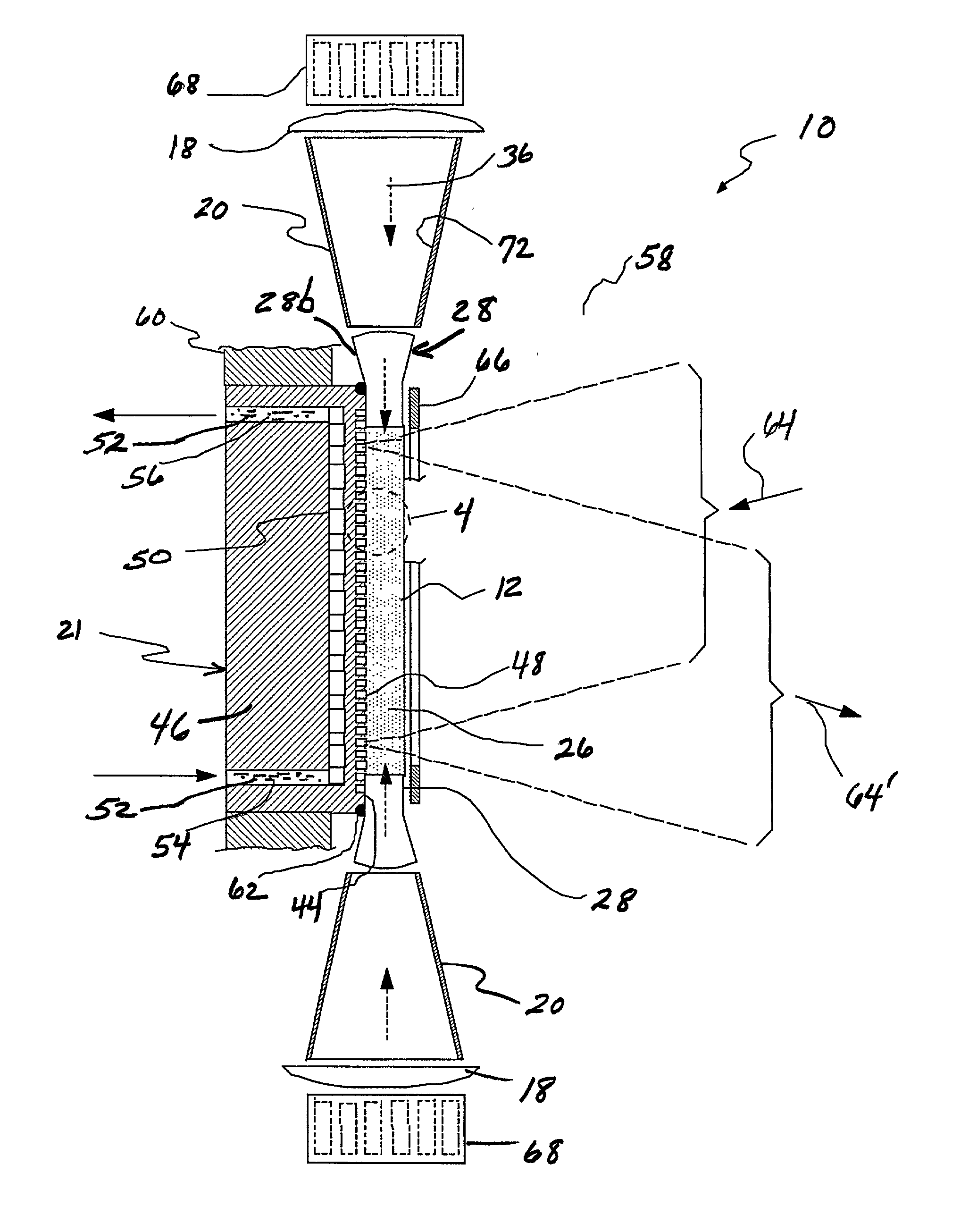
The intensity of the optical output of
diode arrays (lensed or unlensed) is frequently insufficient to pump a SSL gain medium to inversion, and the radiation must therefore be further concentrated.
The surfaces of the laser gain medium that receive pump radiation are susceptible to overheating and, as a result, to excessive thermal stresses.
Due to the exponential absorption of pump radiation, portions of the laser gain medium that are closer to the pump source are susceptible to being pumped more intensely than portions that are further away.
Non-uniform deposition of pump energy results in non-uniform gain.
Gain non-uniformities across the laser beam aperture (normal to the laser beam axis) are highly undesirable as they lead to degradation of beam quality.
In prior art devices, non-uniform pump absorption has been compensated for in a side-pumped rod laser by the gain medium being fabricated with a radially varying level of doping.
Achieving high uniformity of gain becomes even more challenging as the incident laser beam causes saturation-induced change in the
spatial distribution of gain.
ASE depopulates the upper
energy level in an excited laser gain medium and robs the laser of its power.
Furthermore, reflection of ASE photons at gain medium boundaries may provide feedback for parasitic oscillations that aggravate the loss of laser power.
If unchecked, ASE may become large enough to deplete the upper level inversion in high-gain
laser amplifiers.

