Solid-state laser device

A solid-state laser, laser light source technology, applied in lasers, solid-state laser parts, laser parts and other directions, can solve the problems of base material damage, laser transmittance decline, coating damage, etc., to improve reliability, prevent optical Effects of component aging

Inactive Publication Date: 2008-05-28
MITSUBISHI ELECTRIC CORP
View PDF2 Cites 11 Cited by
  • Summary
  • Abstract
  • Description
  • Claims
  • Application Information

AI Technical Summary

Problems solved by technology

[0002] In solid-state laser devices, there is a problem that the transmittance of laser light decreases due to the contamination of optical components placed in the optical path due to the contamination of dust from outside the optical path.
In addition, the dust adhering to the surface of the optical component scatters the laser light passing through the optical component, resulting in a problem that the light-concentrating performance of the laser light is reduced.
In addition, there is a problem that the laser light is absorbed by the attachment attached to the surface of the optical component, the coating applied on the surface of the optical component is destroyed, and the base material of the optical component is also damaged.

Method used


Image

  • Solid-state laser device
  • Solid-state laser device
  • Solid-state laser device

Examples


Embodiment approach 1

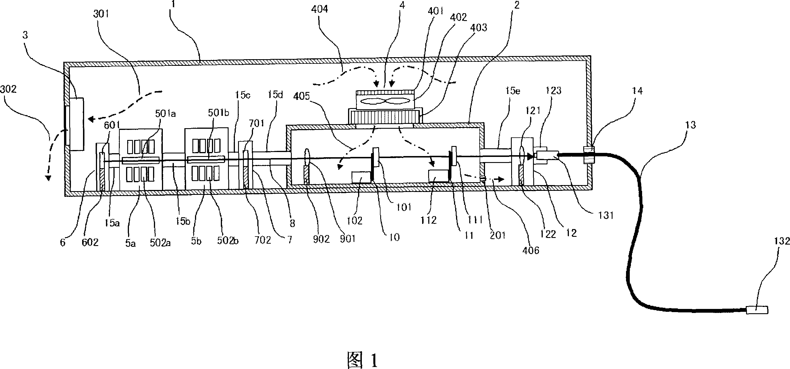
[0020] FIG. 1 is a schematic diagram showing the configuration of a solid-state laser device in Embodiment 1 of the present invention. In FIG. 1 , 1 is an external case having a substantially sealed structure, which also serves as a protective case for preventing leakage of laser light and scattered light to the outside. Here, the substantially airtight structure refers to a structure having airtightness of IP 21 to IP 56 or an equivalent level based on the foreign matter entry level specified in IEC Standard 529 (the same applies below). 2 is an inner case disposed inside the outer case 1 . 3 is a dehumidifier installed on the side wall surface of the outer case 1 as a dehumidification unit, and discharges moisture in the outer case 1 to the outside of the outer case 1 . 301 and 302 are dotted lines schematically showing the water 301 inside the outer case 1 and the water 302 discharged out of the outer case 1 . In addition, in the present embodiment, "SP dehumidifier port ...

Embodiment approach 2

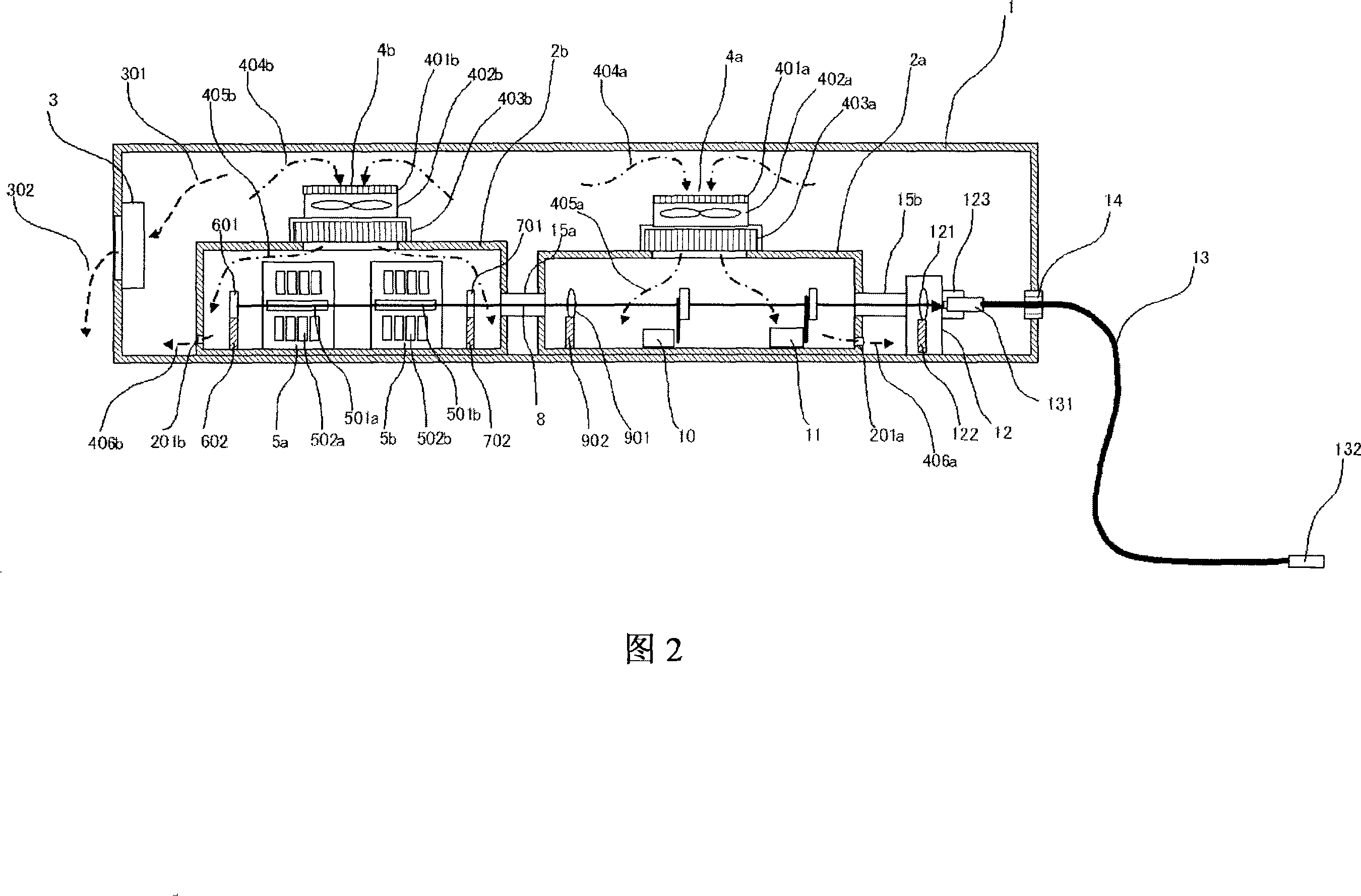
[0029] FIG. 2 is a schematic diagram showing the configuration of a solid-state laser device according to Embodiment 2 of the present invention. In this embodiment, two inner cases 2a and 2b are provided in a single outer case 1 having a substantially airtight structure. In the first inner casing 2a, the collimator lens 901, the intermediate light shielding unit 10, and the safety light shielding unit 11 are arranged in the same manner as in the above-mentioned first embodiment. In addition, a laser light source including two resonator units 5 a and 5 b , a total reflection mirror 601 , and a partial reflection mirror 701 is arranged in the second inner casing 2 b.

[0030] As shown in this embodiment, since a plurality of inner casings 2a, 2b are provided in a single outer casing 1, not only the same effect as that of the above-mentioned first embodiment can be obtained, but also by arranging the inner casing 2b Resonant cavity unit 5a, 5b, not only can reduce the requiremen...

Embodiment approach 3

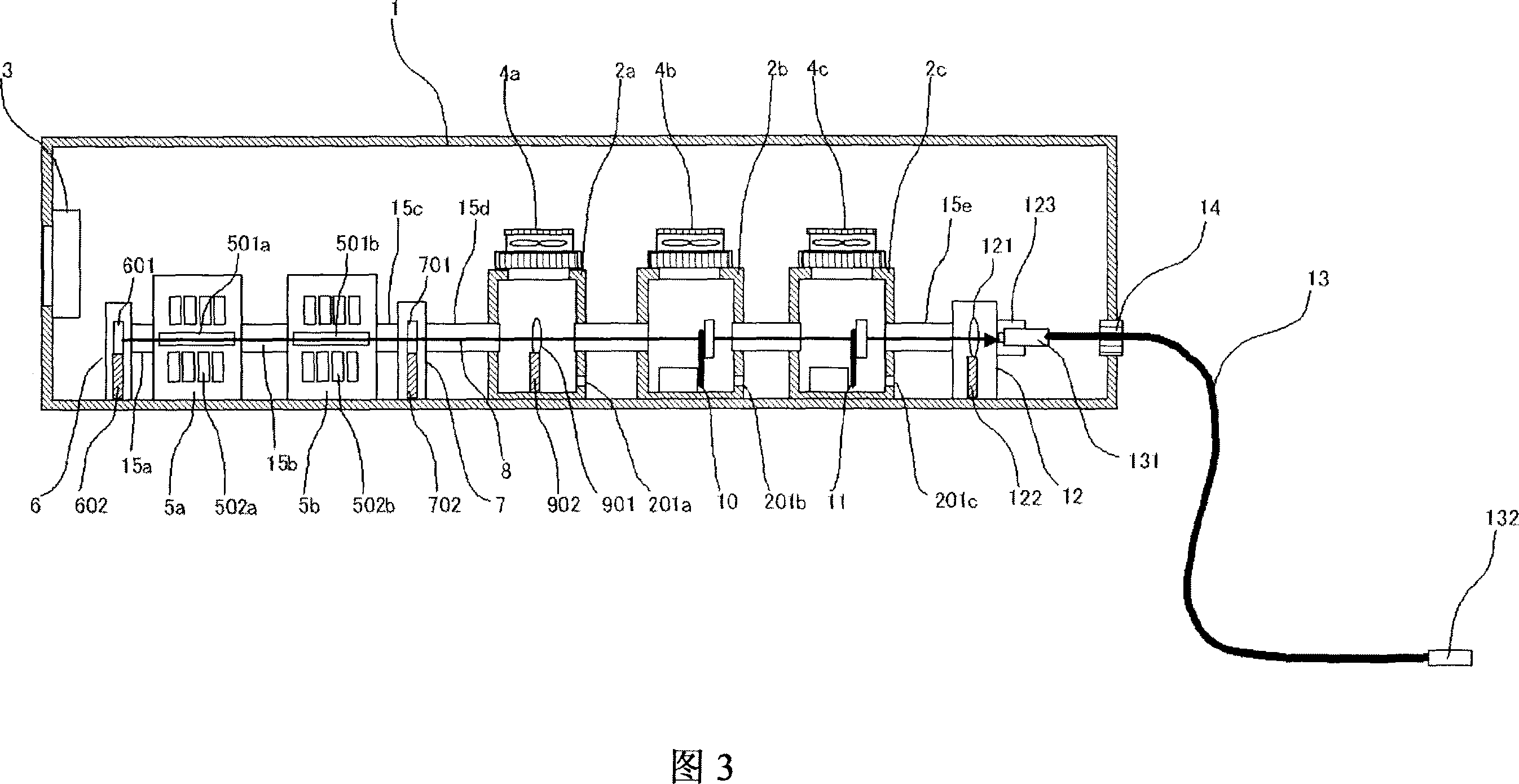
[0035] 3 is a schematic diagram showing the configuration of a solid-state laser device in Embodiment 3 of the present invention. In this embodiment, internal housings 2a, 2b, 2c are provided for collimator lens 901, intermediate light shielding unit 10, and safety light shielding unit 11 constituting the optical system unit for transmitting laser light 8 to optical fiber 13, respectively. According to this embodiment, not only can the same effect as that of the above-mentioned Embodiment 1 and Embodiment 2 be obtained, but also since the inner casings 2a, 2b, and 2c are provided for each unit, when performing maintenance work on each unit, it only needs to be opened as The inner case 2 of the target unit part is enough, so the risk of dust and the like entering into the inner case 2 of other units can be effectively reduced, and the reliability can be further improved.

[0036] In addition, in this embodiment, the collimator lens 901, the intermediate light-shielding unit 10,...


PUM


Abstract

In a solid state laser device, the device has a single outer housing (1) with a substantially enclosed structure, one or more inner housings (2) are disposed in the outer housing (1), an air purification unit (4) for purifying air and feeding the purified air to the inner housing (2) is provided at a part or the entire part of the inner housing (2), laser light sources (5, 6, 7) including a solid state laser medium (501) and an optical resonator and also including optical systems (10, 11, 901) for transmitting or blocking laser light (8) emitted from the laser light sources are arranged in the outer housing (1), and the laser light sources (5, 6, 7) and the optical systems (10, 11, 901) or a part of the optical systems are received in the inner housing (2). The solid state laser device is simple in structure, small in size, and inexpensive, and also, the device is constructed so that degradation of optical parts and moisture condensation are prevented and that it can supply laser light stably.

Description

technical field [0001] The present invention relates to high reliability of solid-state laser devices. Background technique [0002] In a solid-state laser device, there is a problem that the transmittance of laser light is lowered due to contamination of optical components provided in the optical path by dust from outside the optical path. In addition, the dust adhering to the surface of the optical member scatters the laser light passing through the optical member, thereby causing a problem of lowering the focusing performance of the laser light. In addition, there is a problem that laser light is absorbed by deposits adhering to the surface of the optical component, which destroys the coating applied on the surface of the optical component, and at the same time causes damage to the base material of the optical component. [0003] Therefore, in existing solid-state laser processing devices, in order to remove dust, optical elements are arranged in a sealed container, and ...

Claims


Application Information

Patent Timeline
Patent Type & Authority Applications(China)
IPC IPC(8): H01S3/02
CPCH01S3/117H01S3/005H01S3/0092H01S3/025H01S3/0941H01S3/07H01S3/027
Inventor 藤川周一加野润二久场一树
Owner MITSUBISHI ELECTRIC CORP
Why Eureka
Try Eureka