Solid-state laser apparatus, fiber amplifier system, and solid-state laser system

a laser system and laser technology, applied in the direction of laser details, electrical equipment, active medium shape and construction, etc., can solve problems such as resolution drop

Inactive Publication Date: 2017-11-23
THE UNIV OF TOKYO +1
View PDF8 Cites 11 Cited by
  • Summary
  • Abstract
  • Description
  • Claims
  • Application Information

AI Technical Summary

Problems solved by technology

Since a spectral line width in free oscillation of each of the KrF excimer laser unit and the ArF excimer laser unit is wide, e.g., in a range from about 350 μm to about 400 μm, color aberration of laser light (ultraviolet light) that is reduced and projected on the wafer by the projection lens on the exposure apparatus side occurs, which results in decrease in resolution.

Method used


Image

  • Solid-state laser apparatus, fiber amplifier system, and solid-state laser system
  • Solid-state laser apparatus, fiber amplifier system, and solid-state laser system
  • Solid-state laser apparatus, fiber amplifier system, and solid-state laser system

Examples


first embodiment

3. First Embodiment

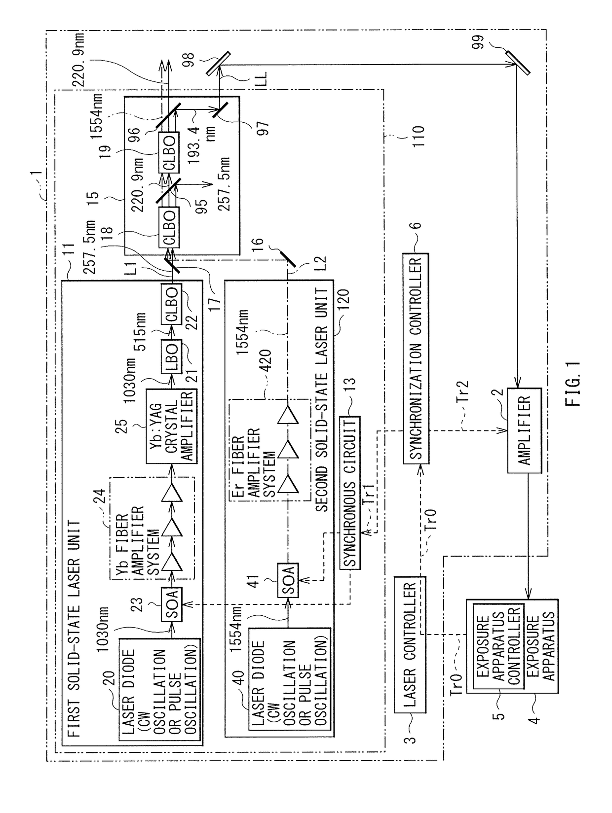
[0088]Next, description is given of a solid-state laser apparatus according to a first embodiment of the present disclosure. Note that substantially same components as the components of the second solid-state laser unit 120 according to the foregoing comparative example illustrated in FIG. 1 are denoted by same reference numerals, and redundant description thereof is omitted.

3.1 Configuration

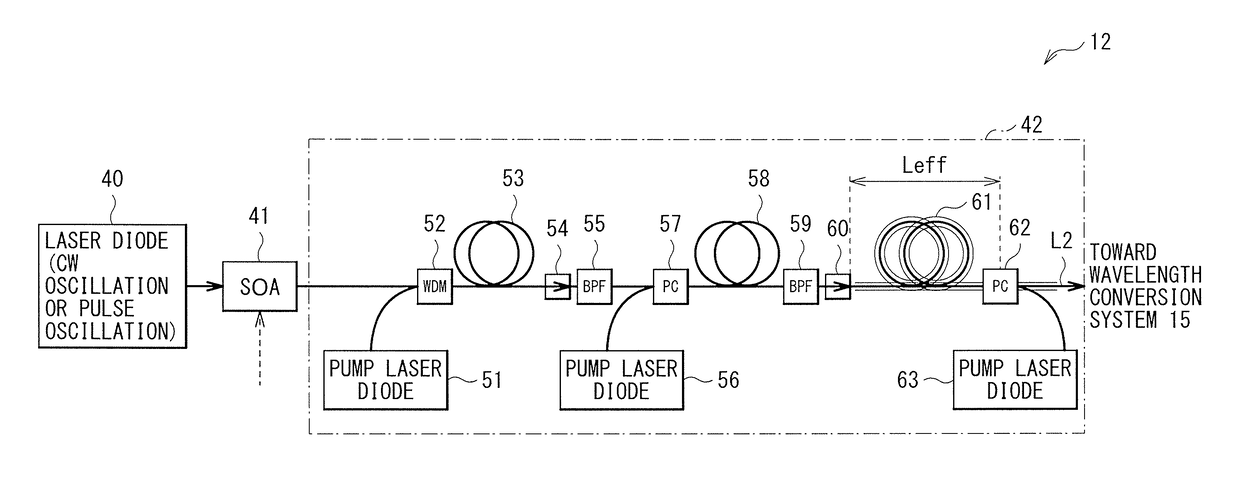
[0089]FIG. 3 schematically illustrates a configuration example of a second solid-state laser unit 12. The second solid-state laser unit 12 may include an Er fiber amplifier system 42 in place of the Er fiber amplifier system 420 in the configuration of the comparative example illustrated in FIG. 1.

[0090]The Er fiber amplifier system 42 may include Er fiber amplifiers 53, 58, and 61, isolators 54 and 60, and band-pass filters (BPFs) 55 and 59. The Er fiber amplifier 53, the isolator 54, the band-pass filter 55, the Er fiber amplifier 58, the band-pass filter 59, the isolator 60...

third modification example

3.4.3 Third Modification Example

[0128]The number of stages of Er fiber amplifiers in the Er fiber amplifier system 42 is not limited to the number of stages illustrated in FIG. 3, and may be any number, as long as the number of stages is two or more. At least the parameter F in the Er fiber amplifier in the final stage of the plurality of stages of the Er fiber amplifiers may be in a range from 0.7 nm to 1.64 nm both inclusive.

fourth modification example

3.4.4 Fourth Modification Example

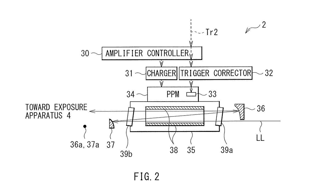
[0129]The amplifier 2 is not limited to the configuration illustrated in FIG. 1. For example, an amplifier 2E including a chamber 47, an output coupling mirror 43, and high reflection mirrors 44 to 46 as illustrated in FIG. 9 may be adopted. Moreover, as with the amplifier 2 illustrated in FIG. 2, although not illustrated, the amplifier 2E may include the amplifier controller 30, the charger 31, the trigger corrector 32, and the pulsed power module 34 including the switch 33. The amplifier 2E may further include a high reflection mirror that guides the pulsed laser light beam LL from the solid-state laser system to the amplifier 2E, or may further include a high reflection mirror that guides a pulsed laser light beam outputted from the amplifier 2E to the exposure apparatus 4.

[0130]The chamber 47 may be provided with windows 49a and 49b. A pair of discharge electrodes 48 may be provided inside the chamber 47. The pair of discharge electrodes 48 may b...


PUM


Abstract

A solid-state laser apparatus may include a first oscillator, a laser light generator, and a plurality of stages of fiber amplifiers. The first oscillator may be configured to output seed light. The laser light generator may be configured to output a pulsed laser light beam generated on a basis of the seed light. The plurality of stages of fiber amplifiers may be disposed in series in an optical path of the pulsed laser light beam, and may include a final stage fiber amplifier. The final stage fiber amplifier may be located in a final stage in the plurality of stages of fiber amplifiers, and may include a silica fiber doped with erbium and ytterbium. A value as a result of division of a cross-sectional area of the silica fiber by a fiber length of the silica fiber may be in a range from 0.7 nm to 1.64 nm both inclusive.

Description

CROSS REFERENCE TO RELATED APPLICATIONS[0001]The present application is a continuation application of International Application No. PCT / JP2015 / 057033 filed on Mar. 10, 2015. The content of the application is incorporated herein by reference in its entirety.BACKGROUND1. Technical Field[0002]The present disclosure relates to a solid-state laser apparatus that generates a pulsed laser light beam, a fiber amplifier system, and a solid-state laser system.2. Related Art[0003]With miniaturization and high integration of a semiconductor integrated circuit, an improvement in resolution has been demanded for a semiconductor exposure apparatus. Hereinafter, the semiconductor exposure apparatus is simply referred to as an “exposure apparatus”. Shortening in a wavelength of light to be outputted from an exposure light source has been in progress accordingly. A gas laser unit is used in place of an existing mercury lamp for the exposure light source. Currently, a KrF excimer laser unit and an ArF...

Claims


Application Information

Patent Timeline
Patent Type & Authority Applications(United States)
IPC IPC(8): H01S3/067H01S3/10
CPCH01S3/06754H01S3/06716H01S3/10015H01S3/06758H01S3/094003H01S3/09415H01S3/1608H01S3/1618H01S3/2316H01S3/2375H01S3/2383H01S3/2391H01S3/0078H01S3/0092H01S3/1643
Inventor ZHAO, ZHIGANGKOBAYASHI, YOHEIITO, SHINJIWAKABAYASHI, OSAMU
Owner THE UNIV OF TOKYO
Why Eureka
Try Eureka