Combined electrical connector

a technology of electrical connectors and combined connectors, which is applied in the direction of electrical apparatus, connection, and coupling device connection, etc., can solve the problems of affecting the assembling process, hindering the minimizing of electronic devices, and not making good use of limited space of electronic devices, so as to facilitate the assembling of combined connectors, and save the inner space of electronic devices

Inactive Publication Date: 2005-05-03
CHENG UEI PRECISION IND CO LTD
View PDF4 Cites 29 Cited by
  • Summary
  • Abstract
  • Description
  • Claims
  • Application Information

AI Technical Summary

Benefits of technology

[0008]Thus, an object of the present invention is to provide a combined electrical connector whose mating ports and electrical cables come out from approximately the same orientation to facilitate assembling the combined connector with an electronic device, and further to save inner space of the electronic device.
[0009]To attain the above object, the present invention provides a combined electrical connector comprises an upper and a lower covers that interlock with each other and define there-between multiple connector receiving cavities arranged side by side. Multiple cable connectors are received in the corresponding cavities side by side for manipulation as a unit. The unit has a mating face wherein define multiple openings and cable apertures beside the openings. Each opening communicates with the corresponding connector receiving cavity. Each cable connector has a mating port at the front end and connects an electrical cable at the rear end. The mating port of each cable connector comes out from the corresponding opening, while the electrical cable comes out from the corresponding cable aperture. So the mating ports and the electrical cables are located in about the same orientation, which facilitates assembling the combined electrical connector with the electronic device and avoid inter-twisting the cable in the device.

Problems solved by technology

So it takes lots of time to assemble and hinders to minimize the electronic device.
However, when the electronic component in the device is located opposite to the orientation of the electrical cable extending, it is inevitable to cause the electrical cable inter-twisting to connect the component in the electronic device.
As a result, it does not make good use of the limited space of the electronic device, and is inconvenient for simplifying assembly.

Method used


Image

  • Combined electrical connector
  • Combined electrical connector
  • Combined electrical connector

Examples


Embodiment Construction

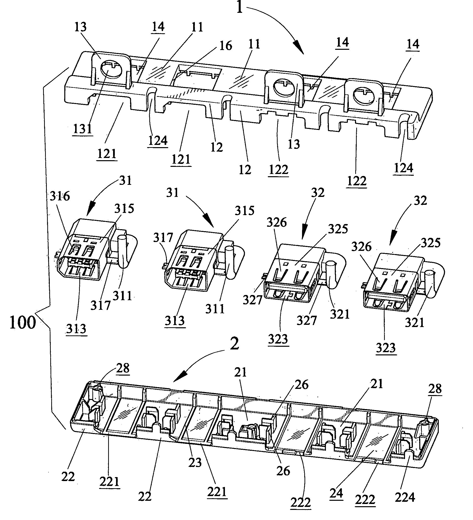
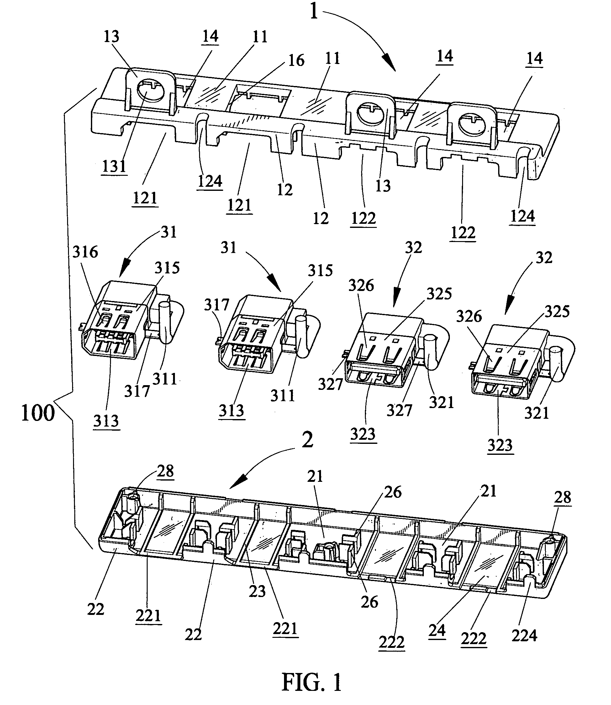
[0018]Referring to FIG. 1, a combined electrical connector 100 comprises an upper and a lower cover 1, 2 that interlock with each other, and multiple cable connectors. The cable connectors are universal type connectors. In the preferred embodiment, the cable connectors include two IEEE (Institute of Electrical and Electronics Engineers) 1394 connectors 31 and two USB (Universal Serial Bus) connectors 32.

[0019]Each of the IEEE 1394 connectors 31 and each of the USB connectors 32 have a mating port 313, 323 at the front end and connects an electrical cable 311, 321 at the rear end. When the combined electrical connector 100 is assembled with an electronic device, the mating port 313, 323 respectively contacts with a mating connector, and the electrical cable 311, 321 electrically connects with electronic components in the device. The IEEE 1394 connectors 31 and the USB connectors 32 respectively have a shielding member 315, 325. The shielding member 315, 325 provides a pair of latch s...


PUM


Abstract

The present invention provides a combined electrical connector comprising an upper and a lower covers that interlock with each other and define there-between multiple connector receiving cavities for multiple cable connectors received therein side by side for manipulation as a unit. The unit has a mating face wherein defines multiple openings and apertures beside the openings. The openings communicate with corresponding cavities. Each cable connector has a mating port at the front end and connects an electrical cable at the rear end. The mating port comes out from the corresponding opening, while the electrical cable comes out from the corresponding aperture. So the mating ports and the electrical cables are located in about the same orientation, which facilitates assembling the combined electrical connector with an electronic device and avoid inter-twisting the cables in the device.

Description

BACKGROUND OF THE INVENTION[0001]1. Field of the Invention[0002]The present invention relates generally to a combined electrical connector, and more especially to a combined electrical connector capable of combing multiple cable connectors side by side to be a unit.[0003]2. The Related Art[0004]Electrical connectors are commonly used in an electronic device to electrically connect periphery electronic components to the electronic device. With the fast development of electronic technology, more and more periphery electronic components are manufactured, so variety types of electrical connectors are largely required. In order to satisfy the consumer, Electronic manufacturers install multiple types of electrical connectors in the electronic devices to provide more mating ports for expanding functions freely. Traditionally, the electrical connectors are assembled with the electronic device one by one. So it takes lots of time to assemble and hinders to minimize the electronic device. Fur...

Claims


Application Information

Patent Timeline
Patent Type & Authority Patents(United States)
IPC IPC(8): H01R13/518H01R13/516
CPCH01R13/518
Inventor LUO, JIZULI, HUA LIAN
Owner CHENG UEI PRECISION IND CO LTD
Why Eureka
Try Eureka