Suction stabilized epicardial ablation devices

a technology of epicardial ablation and suction, which is applied in the field of suction stabilized epicardial ablation devices, can solve the problems of non-conductive lesion, difficult for physicians, and insufficient function of electrical signals

Inactive Publication Date: 2005-05-03
MEDTRONIC INC
View PDF53 Cites 327 Cited by
  • Summary
  • Abstract
  • Description
  • Claims
  • Application Information

AI Technical Summary

Problems solved by technology

Occasionally, these electrical signals do not function properly.
The scar tissue resulting from the procedure results in a non-conductive lesion.
This technique is time-consuming (which is not good for the patient) and requires multiple accurate placements of the electrode (which may be difficult for the physician).
Furthermore, even if the ablation process creates a continuously linear line along the top surface of the target tissue, it is not assured that the tissue is continuously and completely ablated through further layers of the target tissue (i.e. it is not assured that transmurality is achieved).
In addition, it may be difficult to obtain adequate tissue contact pressure for each electrode in a multi-electrode ablation device.
Also, the use of multiple electrodes to create the linear lesion tends to make the tip portion more expensive to make, more bulky and may cause the tip portion to be stiffer than with a single electrode.
Another ablation-related problem results from the delivery of RF energy to muscular tissue, such as the heart Ablation of such tissue using conventional ablation devices has a tendency to char or burn the blood or tissue with which the electrodes are in contact if the temperatures exceed a certain threshold (for example, greater than 50° C.).
This increases the difficulty of the ablation process because it is necessary to clean the tip portion after a series of burns.
Moreover, overheating the tissue in the vicinity of the target site can desiccate the tissue and can cause overburning.

Method used


Image

  • Suction stabilized epicardial ablation devices
  • Suction stabilized epicardial ablation devices
  • Suction stabilized epicardial ablation devices

Examples


Embodiment Construction

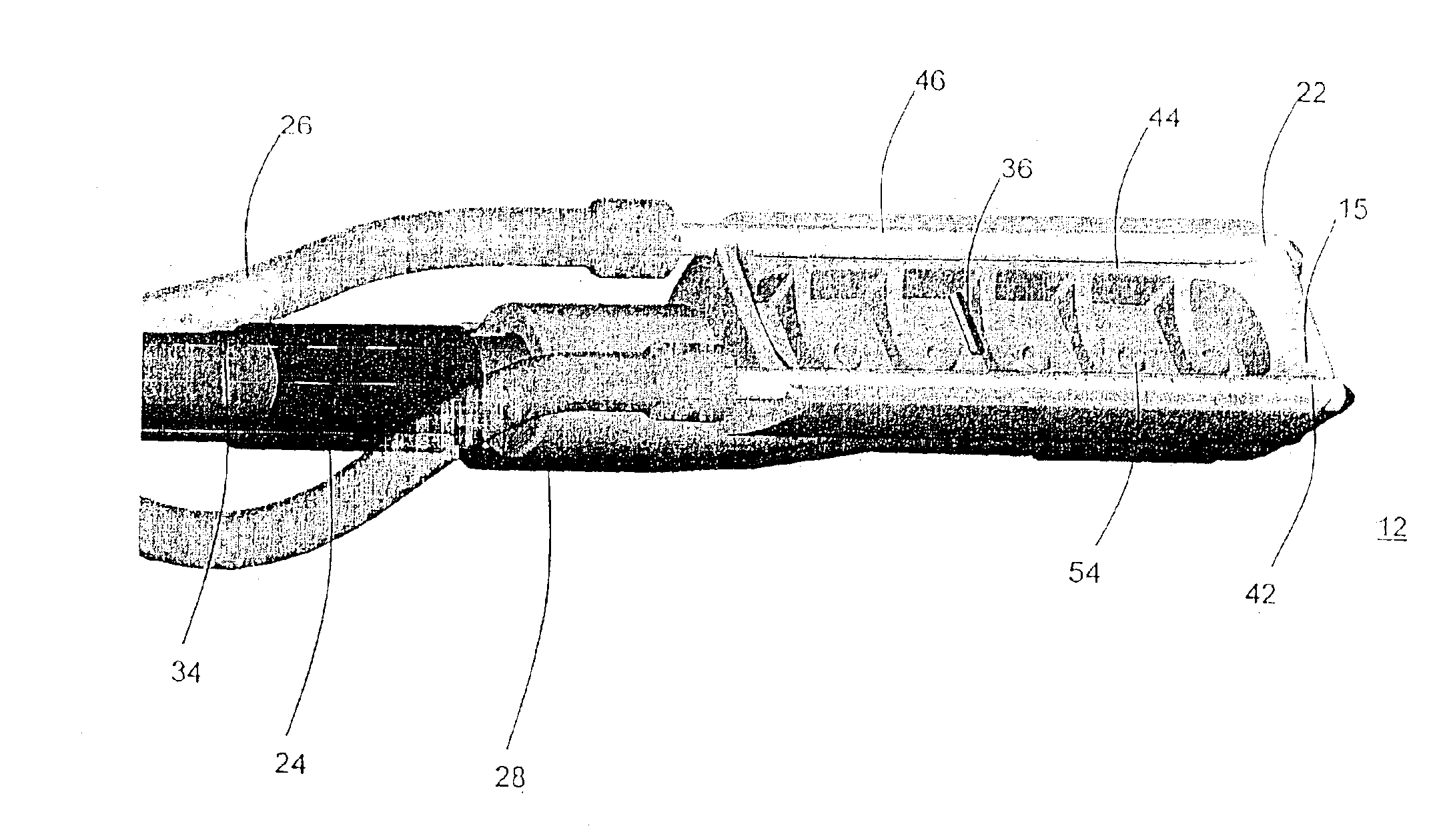
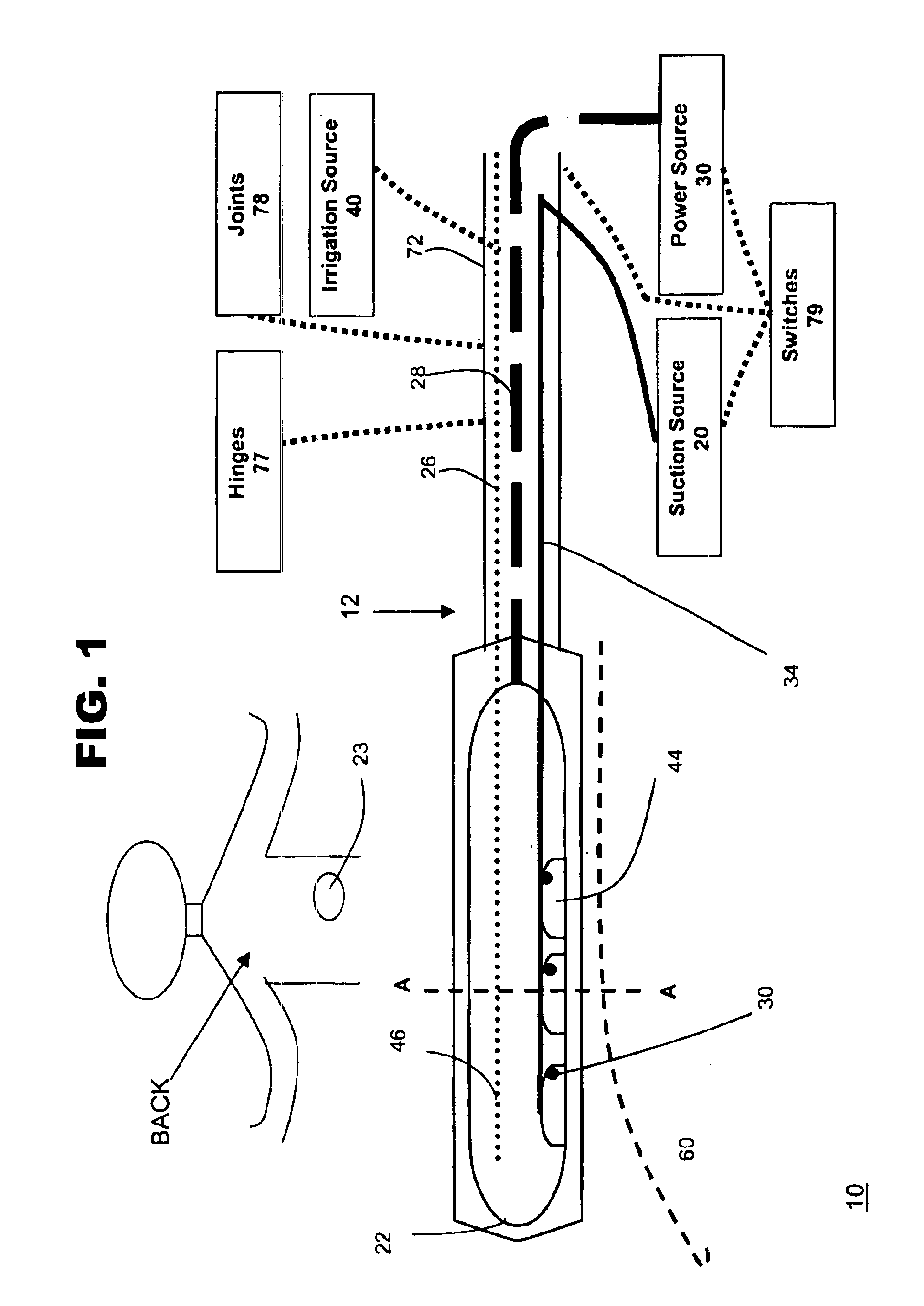
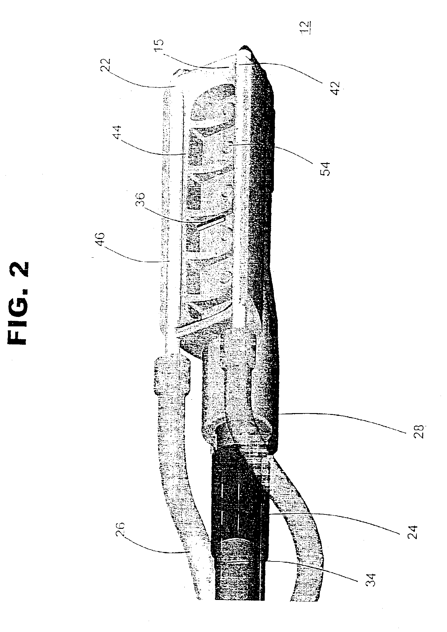
[0031]FIG. 1 shows one embodiment of system 10 for ablating tissue, such as organic tissue, in accordance with the present invention. Typically the tissue to be ablated will be located within the body cavity, such as the endocardial or epicardial tissue of the heart. Other body organ tissue, such as the liver, lungs or kidney, may also be ablated using the present invention. Tissue types that may be ablated include skin, muscle or even cancerous tissue or abnormal tissue growth.

[0032]System 10 may include an ablation device 12 that comprises at least one conductive element 22, such as an electrode, and a connection 28 to a power source 30. Ablation device 12 may also include one or more suction elements 44 and a suction conduit 34 that provides suction from a suction source 20. System 10 also may include a conduit 26 to an irrigation source 40 that provides irrigation fluid to the ablation site. System 10 may also include temperature-sensitive elements 36, which may have the same po...


PUM


Abstract

A suction assisted ablation device having a support surface, suction elements disposed adjacent the support surface, at least one electrode and at least one suction conduit is provided. The device may further include fluid openings, which allow fluid to irrigate target tissue and aid in ablation. A method for ablating tissue using suction is also provided.

Description

CROSS-REFERENCE TO RELATED APPLICATION[0001]This application is a continuation of U.S. patent application Ser. No.: 09 / 843,897, filed on Apr. 26, 2001, now U.S. Pat. No. 6,558,382, which is a continuation-in-part of U.S. patent application Ser. No.: 09 / 558,976, filed on Apr. 27, 2000, now U.S. Pat. No. 6,514,250.FIELD OF THE INVENTION[0002]This invention relates to ablation devices that are used to create lesions in tissue. More particularly, this invention relates to ablation devices that use vacuum or suction force to hold the tissue in a manner that creates [linear] lesions. This invention also relates to diagnostic devices that are used to monitor or evaluate a physiological process. More particularly, this invention relates to diagnostic devices that use vacuum or suction force to hold the device against tissue.BACKGROUND OF THE INVENTION[0003]The action of the heart is known to depend on electrical signals within the heart tissue. Occasionally, these electrical signals do not ...

Claims


Application Information

Patent Timeline
Patent Type & Authority Patents(United States)
IPC IPC(8): A61B18/14A61B17/30A61B17/00A61B17/02A61B18/20A61B18/00A61N1/36
CPCA61B18/1492A61B18/1477A61B2018/1425A61B2017/00053A61B2017/00084A61B2017/00092A61B2017/00203A61B2017/00243A61B2017/00867A61B2017/0243A61B2017/306A61B2018/00011A61B2018/00291A61B2018/00363A61B2018/00577A61B2018/00809A61B2018/00839
Inventor JAHNS, SCOTT E.WERNESS, GREG P.OCEL, JON M.LIPSON, DAVIDJENSEN, DONALD N.FRANCISCHELLI, DAVID E.KEOGH, JAMES R.
Owner MEDTRONIC INC
Why Eureka
Try Eureka