Ultrasonic treatment appliance

a treatment appliance and ultrasonic technology, applied in the field of ultrasonic treatment appliances, can solve the problems of living tissue not being able to be clamped reliably, the force exerted to clamp the living tissue weakens, and the probe is therefore likely to deflect, so as to prevent deterioration of resection and coagulation ability, and minimize the occurrence of nois

Inactive Publication Date: 2005-05-03
OLYMPUS CORP
View PDF10 Cites 315 Cited by
  • Summary
  • Abstract
  • Description
  • Claims
  • Application Information

AI Technical Summary

Benefits of technology

[0033]The first object of the present invention is to provide an ultrasonic treatment appliance making it possible to minimize occurrence of a noise caused by a clamping member that vibrates due to propagated ultrasonic waves, and to improve resection and coagulation abilities.
[0034]The second object of the present invention is to provide an ultrasonic treatment appliance making it possible to prevent deterioration of resection and coagulation abilities caused by heat stemming from ultrasonic vibrations and to maintain the durability of a clamping member.
[0035]The third object of the present invention is to provide an ultrasonic treatment appliance capable of exerting a sufficient quantity of clamping force at the time of clamping a living tissue using a clamping member, eliminating the fear that the living tissue may come off from the clamping member, clamping the living tissue reliably, and offering improved resection and coagulation abilities.
[0036]The fourth object of the present invention is to provide an ultrasonic treatment appliance having a

Problems solved by technology

The probe is therefore likely to deflect when a load is applied by the clamping member.
When the clamping member is used to clamp a living tissue, force exerted to clamp the living tissue weakens.
The living tissue cannot therefore be clamped reliably and may come off from the clamping member.
As a result, the work of resecting the living tissue becomes hard to do.
This poses a problem of deteriorated workability.
If the clamping member is thermally deformed, force exerted to clamp a living tissue weakens.
Consequently, the living tissue cannot be clamped reliably and may come off from the clamping member.
As a result, the work of resecting the living tissue becomes hard to do.
This poses a problem of deteriorated workability.
If the clamping member is made of a resin material such as so-called Teflon and is thin, the resin clamping member is liable to be damaged, that is, deformed, melted to be burnt, or worn out because of heat generated during ultrasonic treatment and clamping force.
Even if the clamping member is made thick, the resin material is inferior in durability to metals or the like from both thermal and mechanical viewpoints.
Even if the thickness of a clamping member made of a resin material were increased, durability would not drastically improve.
As mentioned above, a clamping member made of a resin material is inferior in durability to any metallic clamping member from both thermal and mechanical viewpoints.
This poses a problem that ultrasonic treatment cannot be conducted with high power and treatment efficiency is hard to improve.
This results in a violent loud mechanical sound.
Consequently, the meeting portion of the vibration propagation member is worn out.
The friction results in abrasion.
However, the phase of the base material is affected.
The performan

Method used


Image

  • Ultrasonic treatment appliance
  • Ultrasonic treatment appliance
  • Ultrasonic treatment appliance

Examples


first embodiment

[0083]Referring to FIGS. 1 to 9, the present invention will be described.

[0084]In this embodiment, an ultrasonic incision / coagulation appliance is taken as an example of an ultrasonic treatment appliance.

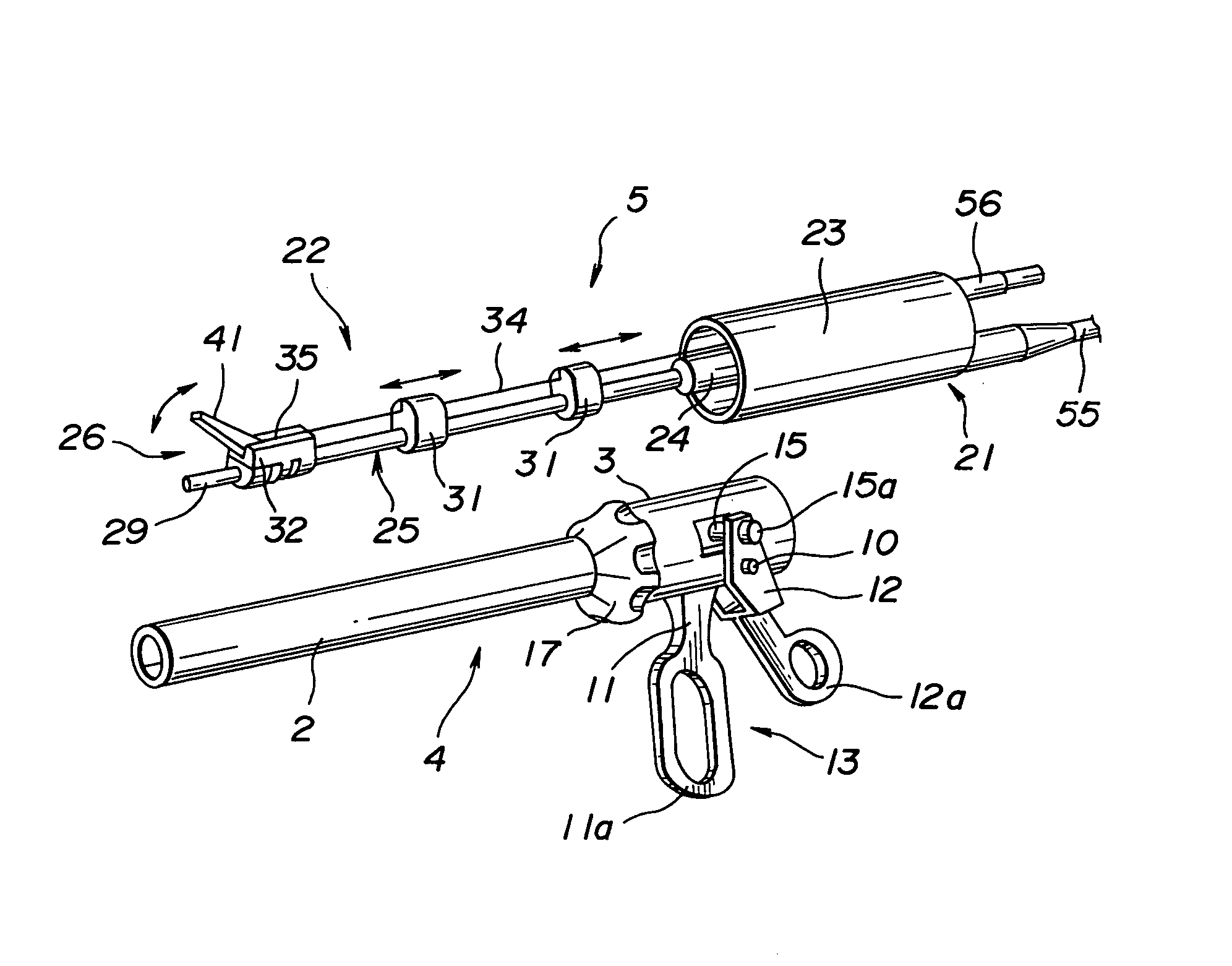
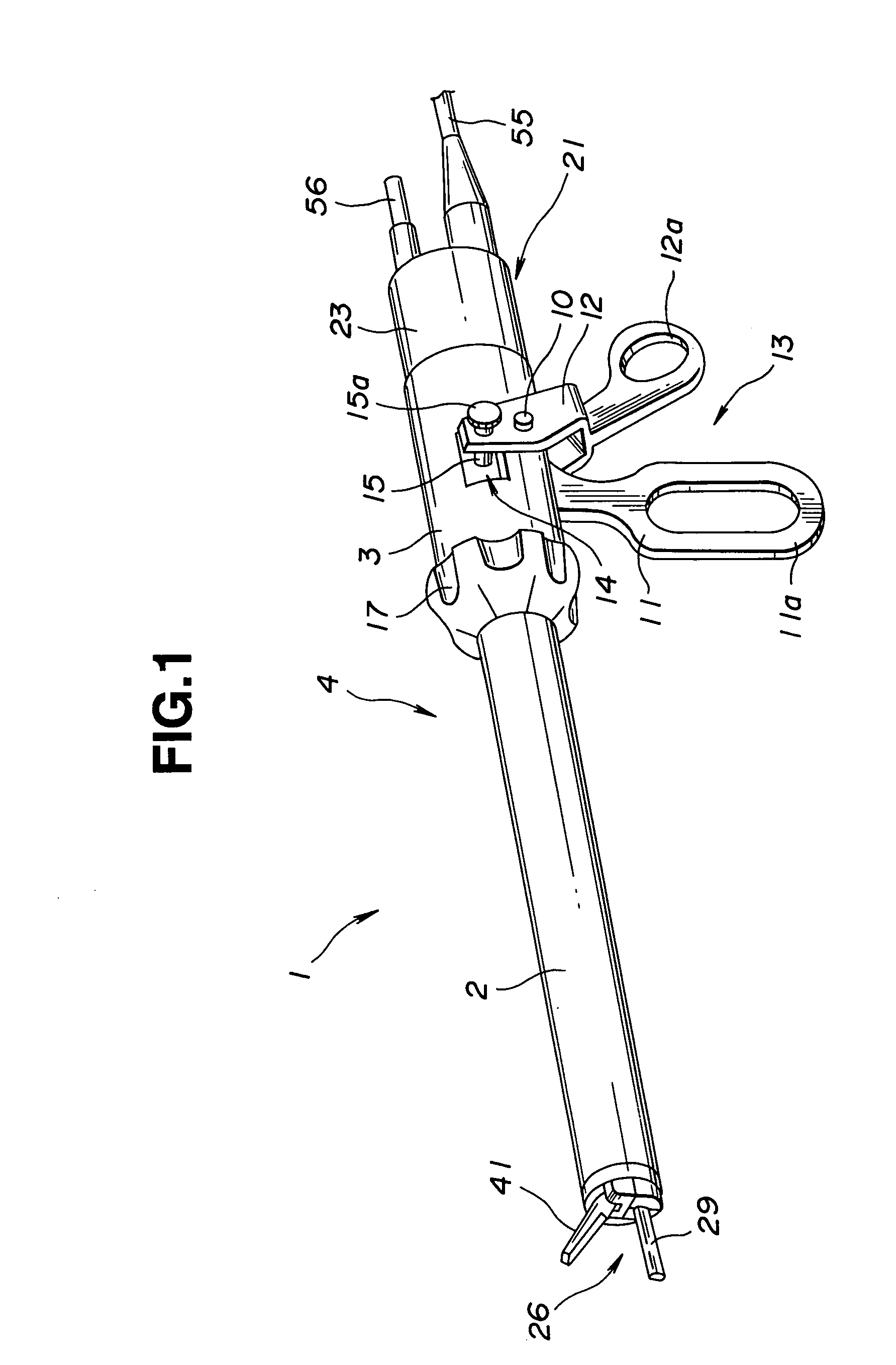
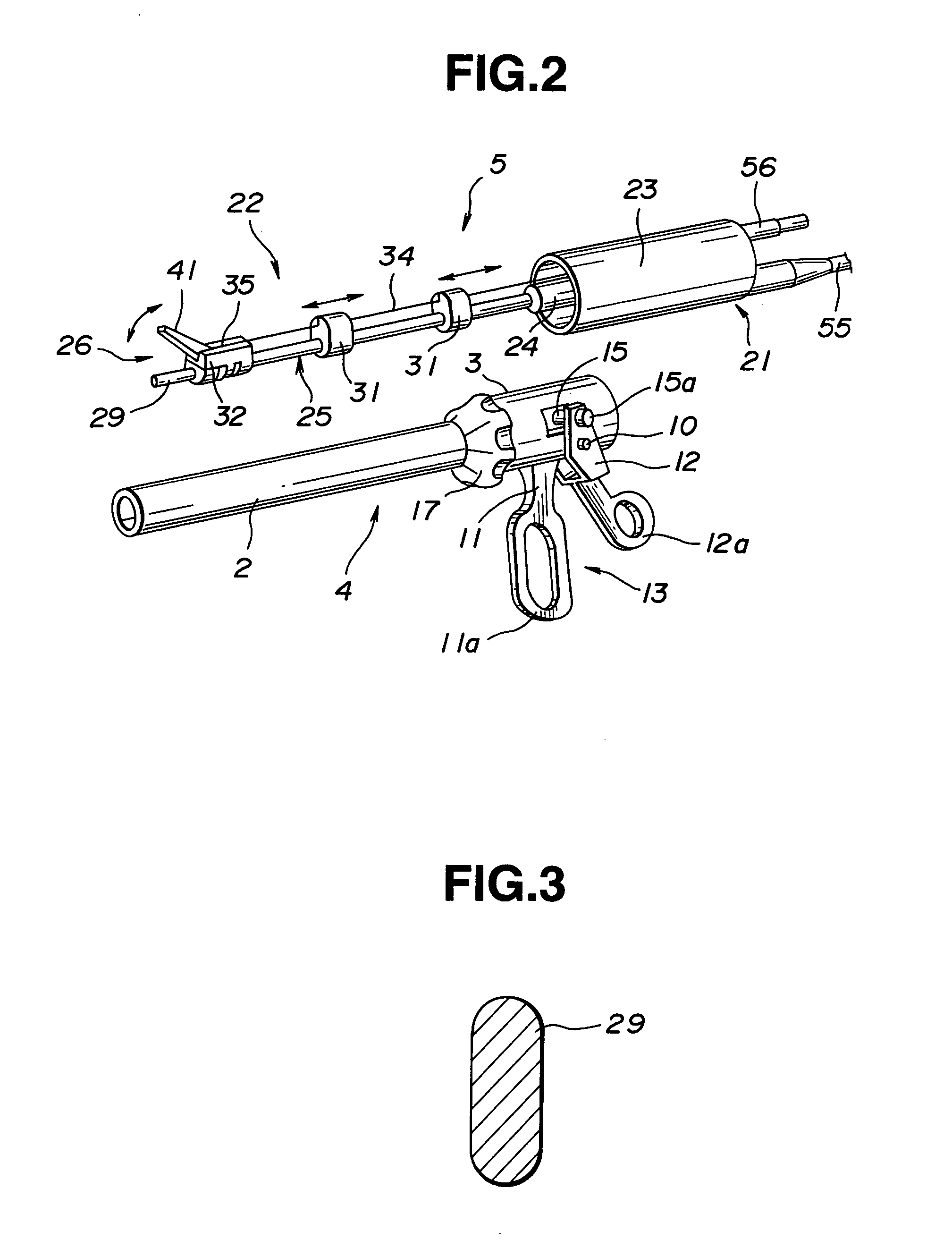
[0085]As shown in FIG. 1, an ultrasonic incision / coagulation appliance 1 has a main unit of a handpiece (main unit of a treatment appliance) 4 including an elongated cylindrical sheath 2 that is an insertion unit protecting member and a cylindrical grip sheath 3 located proximally to the sheath 2. A treatment unit 5 is mounted in the main unit 4 so that the treatment unit 5 can be dismounted freely (See FIG. 2).

[0086]The grip sheath 3 includes an operation unit 13 composed of a stationary handle 11 and movable operation handle 12. The stationary handle 11 is fixed to the grip sheath 3, while the movable operation handle 12 is attached to the grip sheath 3 by a pin 10 so that the movable operation handle 12 can pivot freely. The movable operation handle 12 can therefore pivot freely...

second embodiment

[0133]Referring to FIG. 12, the present invention will be described.

[0134]In this embodiment, the structure in which a thin chip is attached to a jaw body is different from that in the first embodiment. The other components of this embodiment and the operation thereof are identical to those of the first embodiment. The same reference numerals are assigned to the same members. The description of the members will be omitted.

[0135]As illustrated, a metallic thin chip 52a is affixed to the bottom of the clamping ditch 51 formed in the jaw body 40, and the proximal portion of the thin chip 52 is fixed to the jaw body 40 using a screw 71. For preventing the head of the screw 71 from jutting toward the clamping side of the jaw body, the proximal portion of the clamping ditch 51 of the jaw body 40 is formed as a recess 72 that is deeper than the thickness of the head of the screw 71. The proximal portion of the thin chip 52 is screwed in this recess 72.

[0136]Since the thin chip 52 is fixed...

third embodiment

[0137]Referring to FIG. 13, the present invention will be described.

[0138]In this embodiment, the structure in which a thin chip is attached to a jaw body is different from those in the first and second embodiments. The other components of this embodiment and the operation thereof are identical to those of the aforesaid embodiments. The same reference numerals are assigned to the same members. The description of the members will be omitted.

[0139]As illustrated, fitting grooves 73 to which the side margins of a thin chip 52b are fitted and fixed are bored on both right-hand and left-hand sides of the bottom of the clamping ditch 51 formed in the jaw body 40. In other words, the width of the thin chip 52b is made larger than the width of the ditch. The side margins of the thin chip 52b are fitted into the fitting grooves 73, whereby the thin chip 52b is attached to the jaw body 40 in order to construct the jaw 41.

[0140]Since the thin chip 52b is thus fixed to the jaw body 40 by fitti...


PUM


Abstract

An ultrasonic treatment appliance includes a handpiece with a built-in ultrasonic transducer, and an elongated probe extending forward from the handpiece and connected to the ultrasonic transducer in order to propagate ultrasonic vibrations. The ultrasonic treatment appliance further comprises a distal probe part formed as an integral part of or independently of the probe at the distal end of the probe, and a clamping portion opposed to the distal probe part so that the clamping portion can open or close freely, the clamping portion being freely attachable thereto or detachable therefrom.

Description

[0001]This application is a divisional of prior application Ser. No. 09 / 170,266 filed Oct. 13, 1998 now U.S. Pat. No. 6,129,735, which is a continuation-in-part of application Ser. No. 08 / 878,574, filed Jun. 19, 1997, now abandoned.BACKGROUND OF THE INVENTION[0002]1. Field of the Invention[0003]The present invention relates to an ultrasonic treatment appliance for incising, resecting, or coagulating a clamped region by propagating ultrasonic vibrations to a clamping portion that clamps a living tissue.[0004]2. Description of the Related Art[0005]In the past, an ultrasonic therapeutic appliance has been used to resect the prostate, crush calculi, or resect the liver. The ultrasonic therapeutic appliance is constructed by concatenating an ultrasonic transducer, horn, and vibration propagation member. Ultrasonic vibrations generated by the ultrasonic transducer are amplified mechanically by the horn, and transmitted to the vibration propagation member. The distal end of the ultrasonic ...

Claims


Application Information

Patent Timeline
IPC IPC(8): A61B17/32A61B17/28A61B18/14
CPCA61B17/320068A61B17/320092A61B18/1445A61B2017/320088A61B2017/2829A61B2017/2926A61B2017/2825A61B2017/32007A61B2017/320094A61B2017/320071A61B2017/320089A61B2017/320082A61B2017/320069A61B2017/320095A61B2017/320093
Inventor OKADA, MITSUMASAMIYAWAKI, MAKOTOISHIKAWA, MANABU
Owner OLYMPUS CORP
Why Eureka
Try Eureka