Post mold cooling of preforms

Inactive Publication Date: 2005-05-03
MOLD MASTERS 2007
View PDF12 Cites 32 Cited by
  • Summary
  • Abstract
  • Description
  • Claims
  • Application Information

AI Technical Summary

Benefits of technology

[0012]An object of the present invention is to provide an injection molding method and apparat

Problems solved by technology

As noted previously, a key issue is the handling and temperature conditioning of the molded preforms.
Reduced injection molding cycle times may result in soft preforms in which the plastic material may also cryst

Method used


Image

  • Post mold cooling of preforms
  • Post mold cooling of preforms
  • Post mold cooling of preforms

Examples


Embodiment Construction

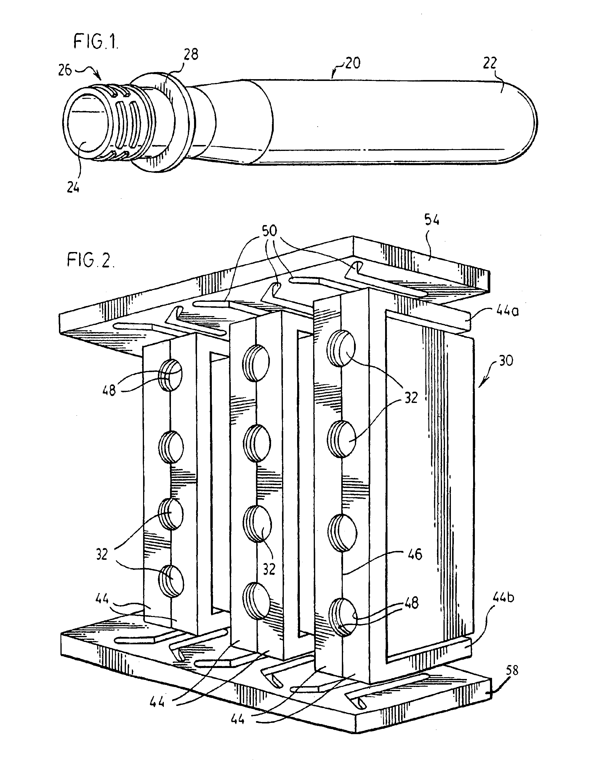
[0038]Referring first to FIG. 1, an injection molded bottle preform is denoted by reference numeral 20 and has a generally cylindrical overall shape with a closed outer end 22 and an open inner end 24. The portion of the preform adjacent end 24 will form the neck of the bottle to be made from the preform and includes a cylindrical threaded section 26 and an annular flange 28.

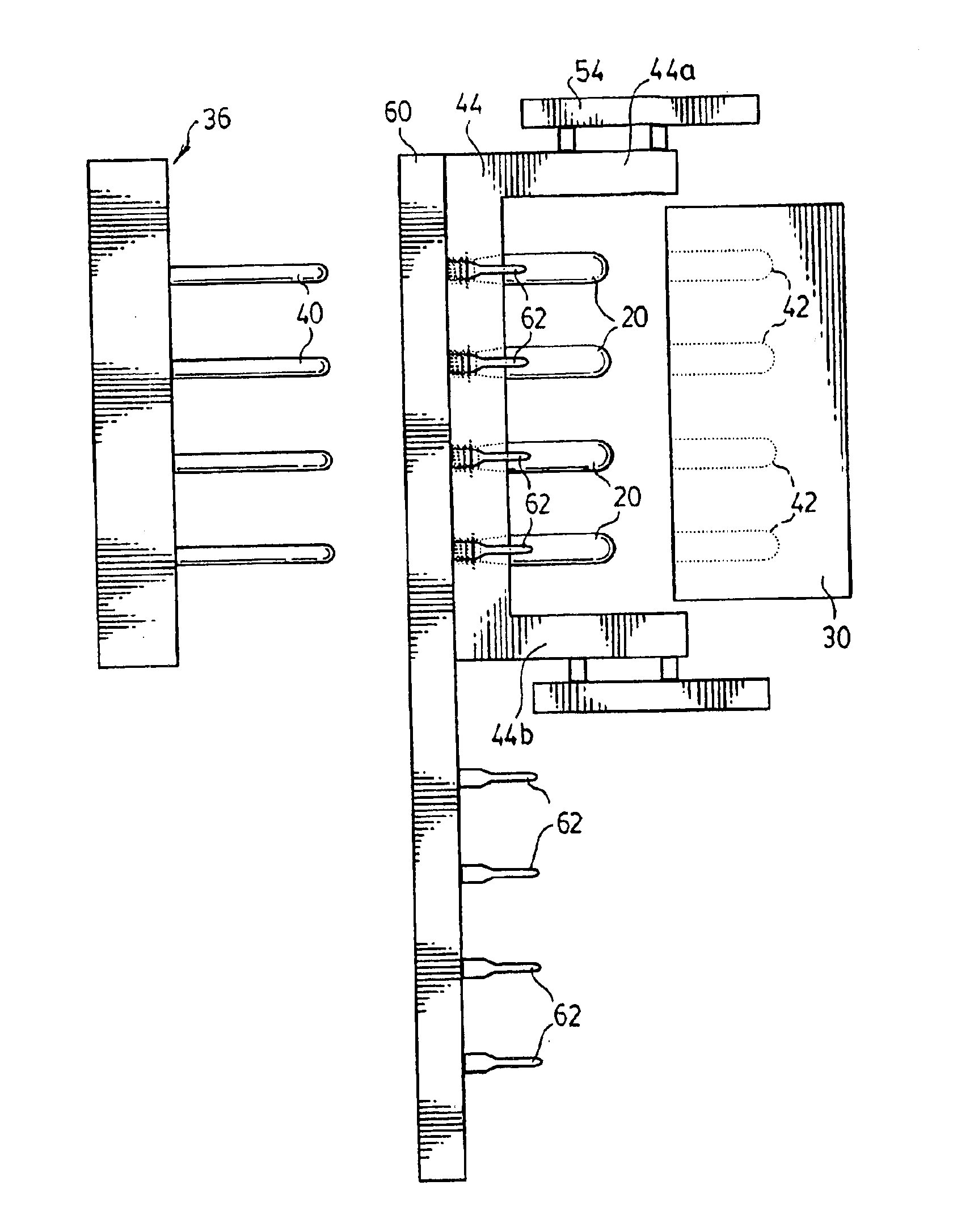
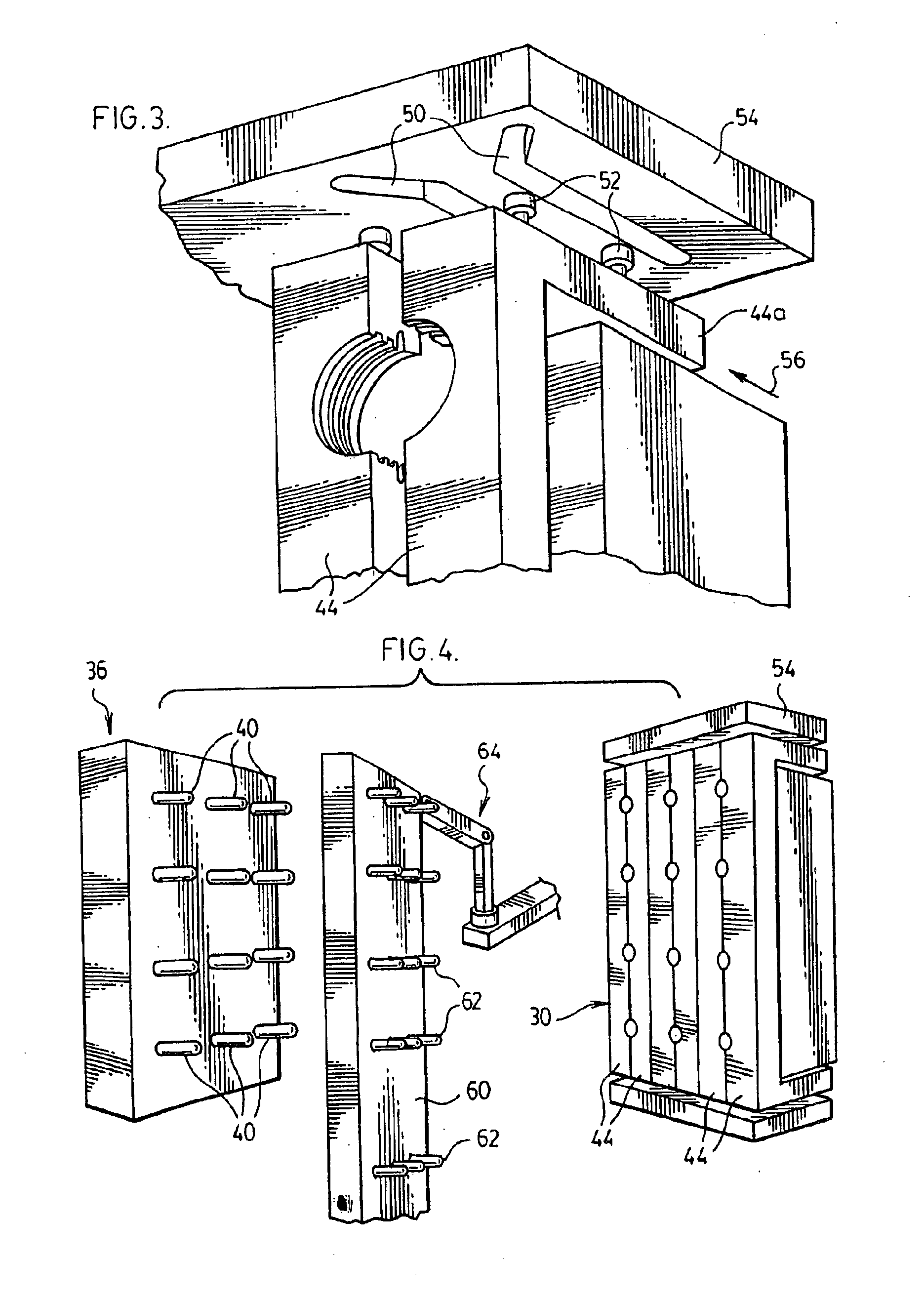
[0039]FIGS. 2 to 6 schematically illustrate the principal components of a molding system for making multiple preforms 20 in batches. For purposes of illustration, the drawings show a system for making batches of 12 preforms; in practice, the apparatus will be designed to make much larger batches, as is conventional in the art. FIG. 2 shows the cavity plate of the mold, generally at 30. Open inner ends of the mold cavities (arranged in vertical rows) are visible at 32. A conventional hot runner system for delivering molten plastic material to the mold cavities is indicated at 34 in FIG. 6.

[0040]A mold core plate ...


PUM

PropertyMeasurementUnit
Electrical conductoraaaaaaaaaa

Abstract

Post-mold cooling of injection molded plastic articles such as preforms is achieved by transferring the articles directly from the mold cavities onto cooling cores carried by a take-out plate. The molded articles are supported on the cooling cores until they become sufficiently frozen that they can be stripped from the cores.

Description

CROSS-REFERENCE TO RELATED APPLICATIONS[0001]This application claims benefits from U.S. provisional application Ser. No. 60 / 330,541 filed Oct. 24, 2001 which is incorporated herein by reference in its entirety.FIELD OF THE INVENTION[0002]This invention relates generally to the plastic molding art. More particularly (though not exclusively) the invention is concerned with the manufacture of relatively large blow molded hollow articles such as bottles for carbonated drinks.BACKGROUND OF THE INVENTION[0003]Bottles for carbonated drinks typically are made in a wide variety of sizes, including quite large sizes (e.g. 2 litre capacity). These bottles are required to meet rigorous testing standards to guard against the possibility that a bottle might leak or burst in use. The bottles are required to withstand severe, extraordinary mechanical impacts without leaking.[0004]In order to ensure that the finished bottles meet the required standards, close attention is paid to the bottle manufact...

Claims


Application Information

Patent Timeline
IPC IPC(8): B29C45/72B29C45/42B29L22/00
CPCB29C45/42B29C45/7207B29K2105/253B29C2045/7214
Inventor OLARU, GEORGESICILIA, ROBERT
Owner MOLD MASTERS 2007
Why Eureka
Try Eureka