Computer system and method of controlling rotation speed of cooling fan

a computer system and cooling fan technology, applied in the direction of starter details, dynamo-electric motor/converter starters, field or armature current control, etc., can solve the problems of unexpected high temperature of power source circuit, short battery life and unwanted noise, etc., to reduce noise generation and efficient and safe cooling

Inactive Publication Date: 2005-05-03
TOSHIBA CLIENT SOLUTIONS CO LTD
View PDF15 Cites 59 Cited by
  • Summary
  • Abstract
  • Description
  • Claims
  • Application Information

AI Technical Summary

Benefits of technology

[0006]Accordingly, it is an object of the present invention to provide a computer system and a method of controlling a cooling fan, which is capable of reducing the generation of noise and achieving efficient and safe cooling in a computer system including a heat generating element in which a heat generation amount is changed, and another heat generating element.

Problems solved by technology

Also, rotation of a cooling fan results in a shorter battery life and unwanted noise.
Hence, the conventional supposition that “the temperature of the power source circuit is low when the temperature of the CPU is low” is not satisfied.
Therefore, there may be a case where the power source circuit has an unexpectedly high temperature with control based only on the temperature of the CPU.
Peripheral circuits hence may be damaged.

Method used


Image

  • Computer system and method of controlling rotation speed of cooling fan
  • Computer system and method of controlling rotation speed of cooling fan
  • Computer system and method of controlling rotation speed of cooling fan

Examples


Embodiment Construction

[0027]In the following, an embodiment of the present invention will be explained with reference to the drawings.

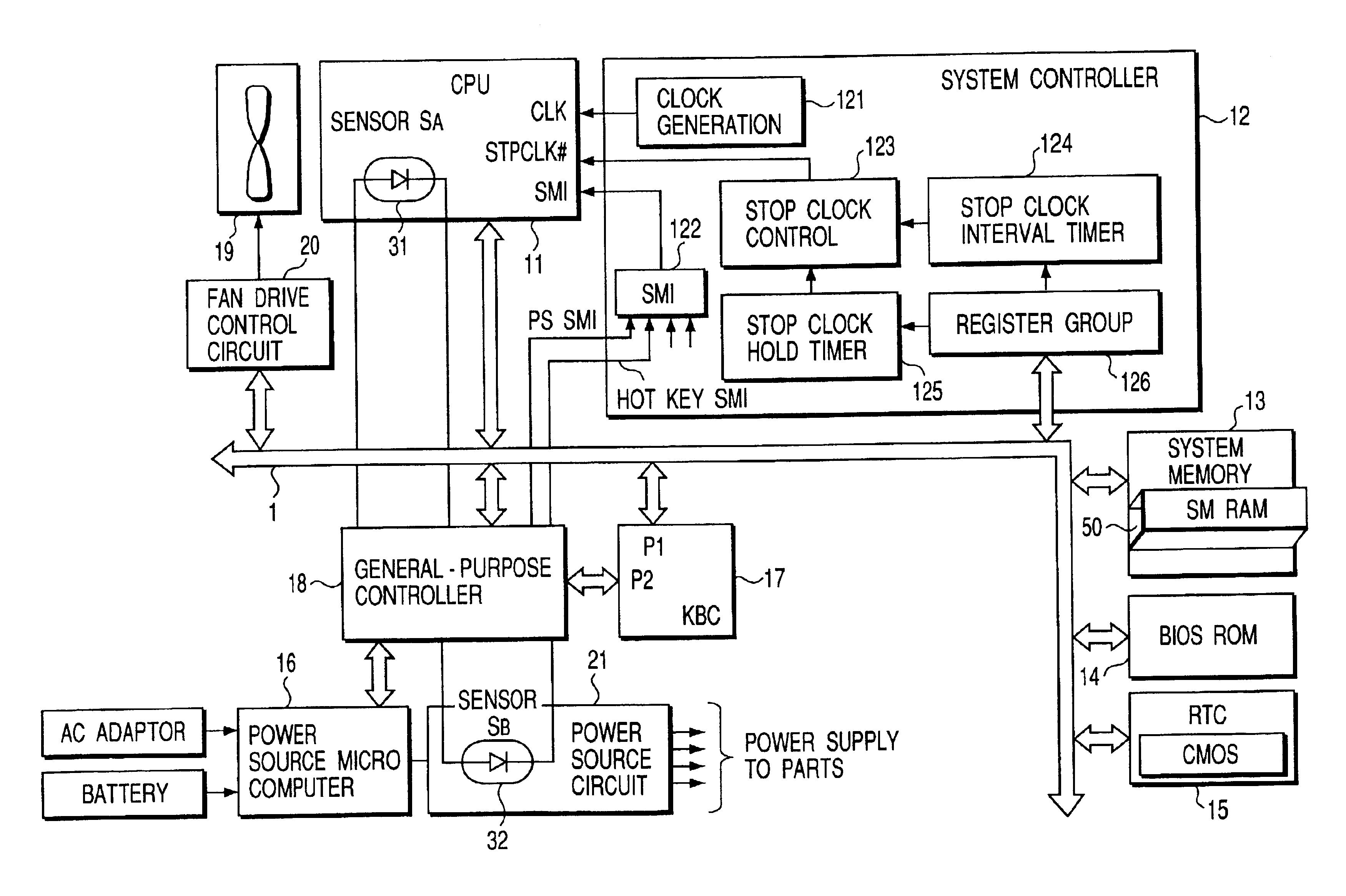
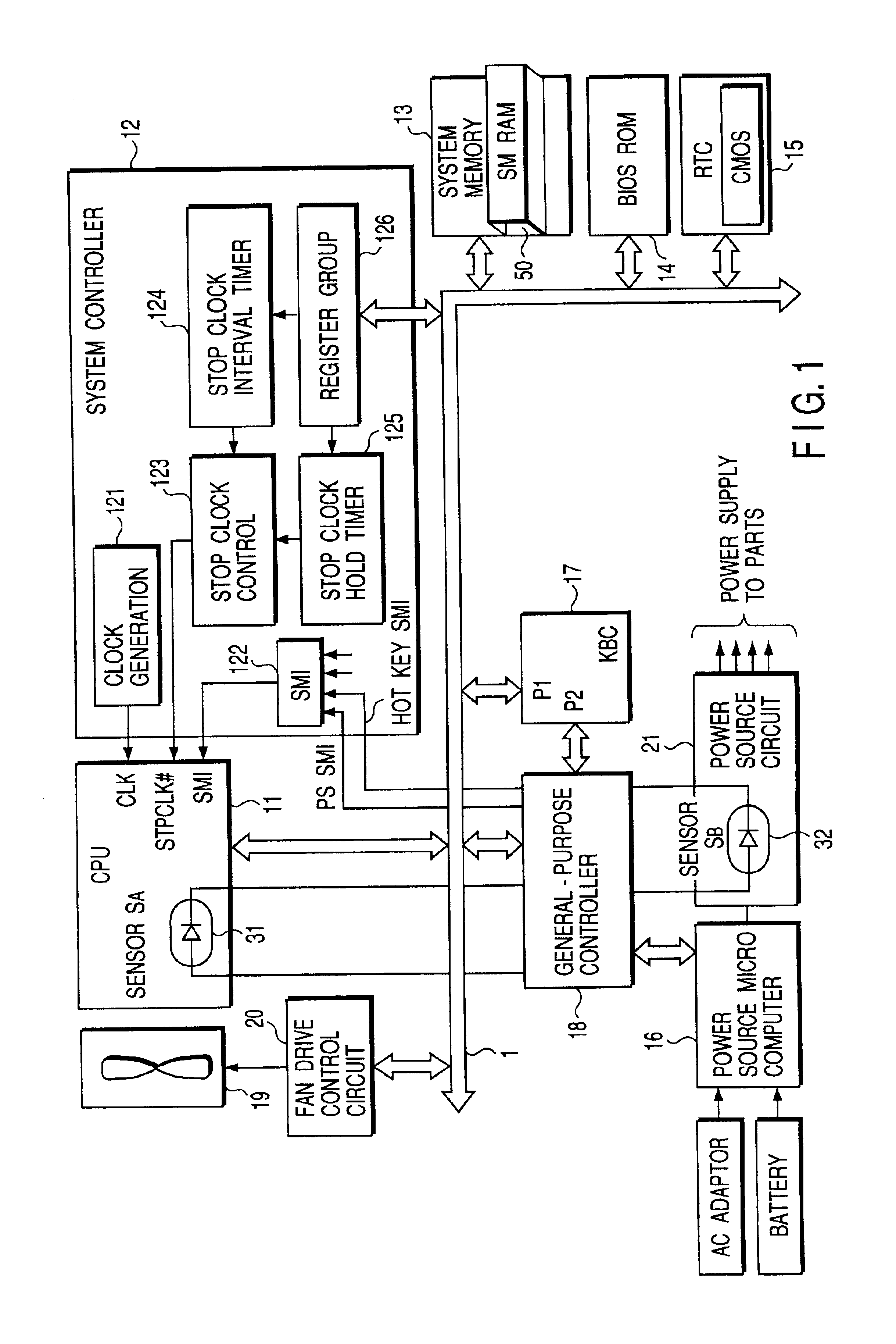
[0028]FIG. 1 is a block diagram showing the structure of a computer system according to the embodiment of the present invention.

[0029]This computer system is, for example, a portable personal computer system of a laptop or notebook type. The system includes a CPU 11, a system controller 12, a system memory 13, a BIOS-ROM 14, a real-time clock (RTC) 15, a power source micro-computer 16, a keyboard controller 17, a general-purpose controller 18, a cooling fan 19, a fan drive control circuit 20, a power source circuit 21, a CPU temperature sensor 31 (which may be hereinafter called a sensor SA), and a power-source-circuit temperature sensor 32 (which may be hereinafter called a sensor SB).

[0030]For example, a microprocessor manufactured by INTEL and adopting SpeedStep™ technology as a power save technique is used as the CPU 11. The CPU 11 includes a PLL circuit. Based on an e...


PUM


Abstract

A computer system includes a first heat generating element in which a heat generation amount is changed, a second heat generating element, a fan configured to cool the first and second heat generating elements, a first temperature sensor configured to detect a temperature of the first heat generating element, a second temperature sensor configured to detect a temperature of the second heat generating element, and a controller configured to control a rotation speed of the cooling fan, based on the temperatures detected by the first and second temperature sensors.

Description

CROSS-REFERENCE TO RELATED APPLICATIONS[0001]This application is based upon and claims the benefit of priority from the prior Japanese Patent Application No. 2000-182349, filed Jun. 16, 2000, the entire contents of which are incorporated herein by reference.BACKGROUND OF THE INVENTION[0002]The present invention relates to a computer system and a method of controlling the rotation speed of a cooling fan, and particularly, to a method for controlling a cooling fan applied to a computer system including a CPU having a power save mode.[0003]In recent personal computer systems of a laptop or notebook type, it is necessary to reduce not only the temperature of the CPU but also the surface temperature of the casing. In particular, it is necessary to reduce an increase of the surface temperature of the casing due to heat generation from the power source circuit. Also, rotation of a cooling fan results in a shorter battery life and unwanted noise. Therefore, it is required to put the fan not...

Claims


Application Information

Patent Timeline
Patent Type & Authority Patents(United States)
IPC IPC(8): G06F1/20H01L23/34G06F1/26H05K7/20
CPCG06F1/206H01L23/34H01L2924/0002H01L2924/00
Inventor MATSUSHITA, SATOSHI
Owner TOSHIBA CLIENT SOLUTIONS CO LTD
Why Eureka
Try Eureka