Obstacle detection device for vehicle and method thereof

a technology for obstacle detection and vehicle, which is applied in the direction of distance measurement, instruments, television systems, etc., can solve the problems of erroneously recognizing obstacles, affecting the merchantability of obstacle detection devices for vehicles, and inconvenient us

Inactive Publication Date: 2005-05-03
TOYOTA JIDOSHA KK
View PDF7 Cites 88 Cited by
  • Summary
  • Abstract
  • Description
  • Claims
  • Application Information

AI Technical Summary

Benefits of technology

[0015]According to the aforementioned construction and method, erroneous recognition of the virtual image created by a reflection on the road surface, as an obstacle, is able to be minimized even when the virtual image is recognized by captured image processing.

Problems solved by technology

Typically, CCD cameras have the benefit of being able to detect lane markings and lights and the like on the road, but are inferior in terms of accuracy with far distances because they calculate distance using a captured image.
Even with an obstacle detection device for a vehicle that uses both a CCD camera and millimeter wave radar, however, there is a possibility that an object, with which there is no danger of collision, may be erroneously recognized as an obstacle due to a virtual image appearing on the image captured by the CCD camera.
At this time, the calculation results from the captured image and the measurement results from the millimeter wave radar are consistent, so the obstacle detection device for a vehicle may recognize these metal objects as obstacles and issue an erroneous warning.
This type of erroneous warning may cause the user to distrust the obstacle detection device for a vehicle, thereby hurting the merchantability of the obstacle detection device for a vehicle.

Method used


Image

  • Obstacle detection device for vehicle and method thereof
  • Obstacle detection device for vehicle and method thereof
  • Obstacle detection device for vehicle and method thereof

Examples


Embodiment Construction

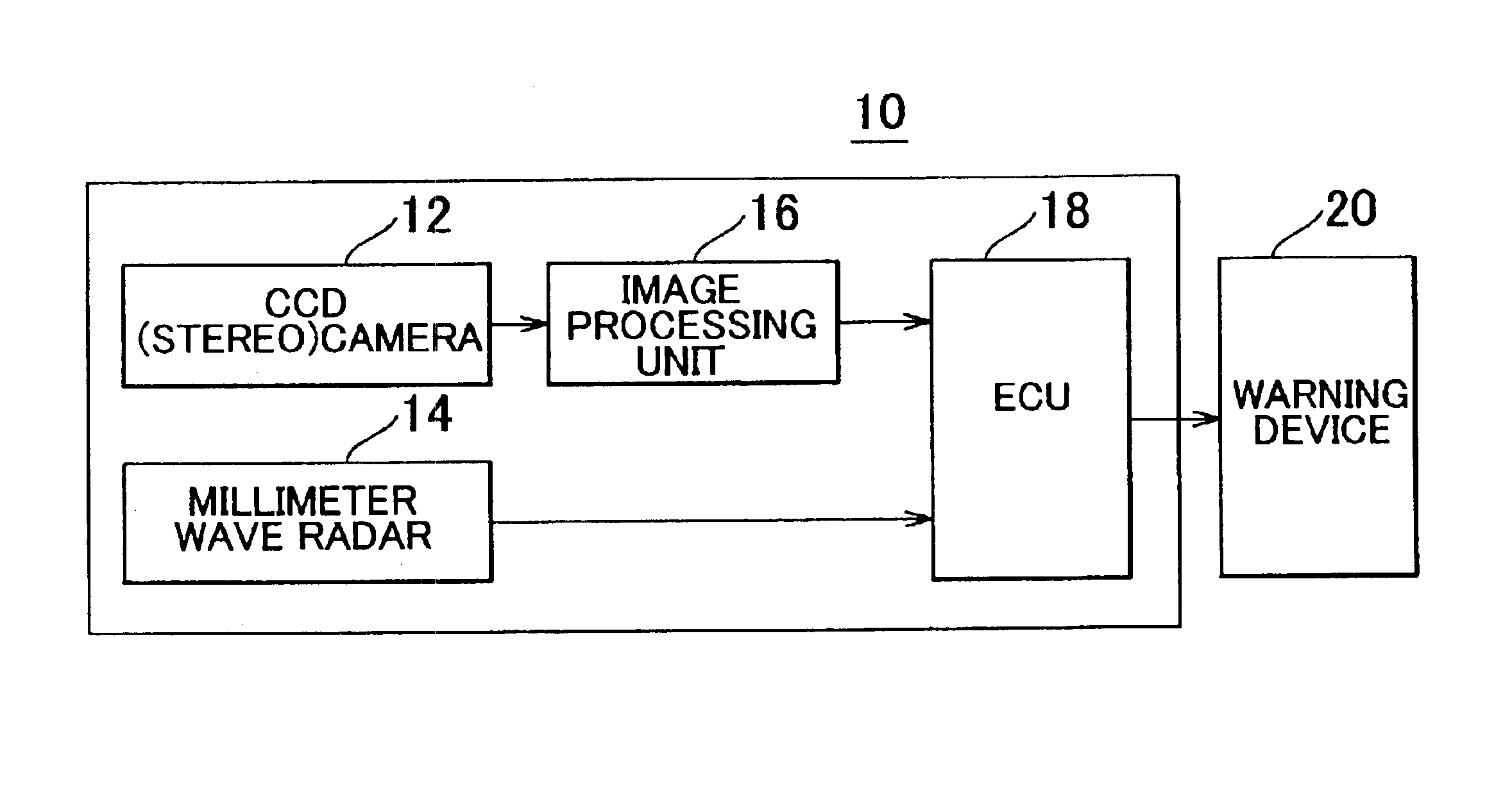
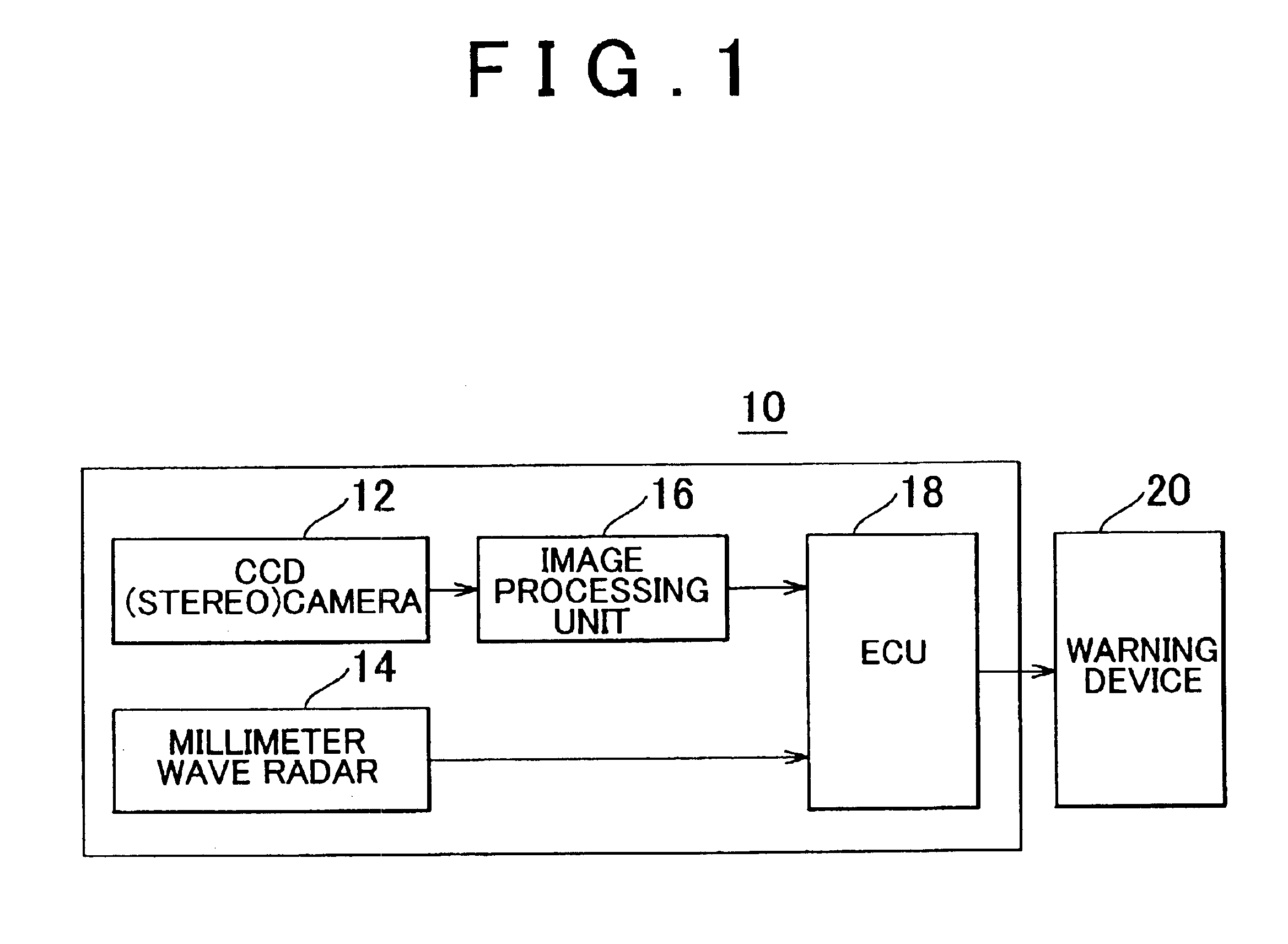
[0021]FIG. 1 is a block diagram of an obstacle detection device 10 for a vehicle according to one exemplary embodiment of the invention. This obstacle detection device 10 for a vehicle is provided with a CCD (stereo) camera (image capturing portion) 12 as imaging means, an image processing unit 16 connected to the CCD camera 12, a radar ranging portion 14 as radar ranging means, and an electronic control unit (ECU) 18 connected to the image processing unit 16 and the radar ranging portion 14. A warning device 20 that issues a warning is also connected to this obstacle detection device 10 for a vehicle.

[0022]The CCD camera 12 is mounted so as to capture an image of an area in front of the vehicle, e.g., the CCD camera 12 is fixed near the rearview mirror inside the vehicle cabin. The image data of the image (hereinafter, this image will be referred to as “captured image”) captured by the CCD camera 12 is sent to the image processing unit 16 at a predetermined interval of time.

[0023]T...


PUM


Abstract

An obstacle detection device for a vehicle that detects obstacles using a distance to an object calculated by image processing and a distance to the object calculated by radar ranging. This obstacle detection device includes a measuring portion that measures an amount of movement of the object at a predetermined interval of time by image processing and a measuring portion that measures an amount of movement of the object at a predetermined interval of time by radar ranging, and does not determine the object to be an obstacle when the two amounts of movement are not consistent.

Description

INCORPORATION BY REFERENCE[0001]The disclosure of Japanese Patent Application No. 2002-050451 filed on Feb. 26, 2002 including the specification, drawings and abstract are incorporated herein by reference in its entirety.BACKGROUND OF THE INVENTION[0002]1. Field of the Invention[0003]The invention generally relates to an obstacle detection device for a vehicle, which is mounted in the vehicle, to help a driver become aware of obstacles and the like. More specifically, the invention relates to an obstacle detection device for a vehicle which minimizes the false recognition of objects that cause virtual images in a captured image.[0004]2. Description of the Related Art[0005]In recent years, the use of CCD cameras and millimeter wave radar has become widespread in order to help a driver become aware of obstacles and the like while driving. Typically, CCD cameras have the benefit of being able to detect lane markings and lights and the like on the road, but are inferior in terms of accu...

Claims


Application Information

Patent Timeline
Patent Type & Authority Patents(United States)
IPC IPC(8): G01S13/00G01S11/00G01S11/12G01S13/34G01S13/93B60R21/01G01S13/86G01C3/06B60R21/00B60R21/0134G01S13/931
CPCG01S11/12G01S13/348G01S13/867G01S13/931B60R21/0134G01S13/86G01S2013/9375G01S2013/9367G01S2013/9353G01S2013/9323G01S2013/93271G01S2013/932G08G1/16
Inventor HORI, YOSHIHITONONAKA, MASAKATSU
Owner TOYOTA JIDOSHA KK
Why Eureka
Try Eureka