Programmable timer unit for use in a remote control load management system

a technology of remote control and load management system, which is applied in the direction of electric controllers, electric programme control, instruments, etc., can solve the problems of increasing the cost of satisfying more sophisticated load management, and achieve the effect of reliable operation of the timer uni

Inactive Publication Date: 2005-05-03
MATSUSHITA ELECTRIC WORKS LTD
View PDF7 Cites 36 Cited by
  • Summary
  • Abstract
  • Description
  • Claims
  • Application Information

AI Technical Summary

Benefits of technology

[0007]Accordingly, it is a primary object of the present invention to provide the programmable timer unit which is capable of controlling a large number of loads, yet at reduced cost and space requirements.
[0009]In a preferred embodiment, the memory is designed to store a sunrise time and a sunset time specific to each of a plurality of predetermined regions. In this connection, the input section provides a menu for selecting one of the regions and for selecting one of the sunrise time and sunset time as the actuation time for the load. The sunrise and sunset times specific to the selected region are read from the memory by the processor which, in response to the present time coming coincident with the selected one of the sunrise and sunset times, generates the event signal for actuating the designated load. Thus, it is easy to manage the load in accordance with the solar schedule specific to the selected region. For the purpose of managing the load in precise match with a particular region, the input section is provided with a means for modifying the sunrise and sunset times
[0011]Preferably, the input section includes a display for items to be selected at the entry of the schedule. The display is controlled by the processor so as to be deactivated after the elapse of a predetermined time period from the last action made at the input section, thereby saving energy.
[0013]The input section may have a simulation means for accepting a simulation request for simulating the load management program, selecting the load management program to be simulated, and providing a simulation command. In response to the simulation command, the processor retrieves the actuation time from the program and temporarily sets the present time as the actuation time for executing the load management program. Thus, the user can easily simulate the load management schedule simply by selecting the program at the input section.
[0015]The programmable timer unit is preferably designed to have a time signal input terminal circuit for receiving a time signal being counted at an external device such a real time signal distributed via the transmission line, and a time signal output terminal for passing the time signal to another programmable timer unit connected through the transmission line. A synchronous time correction means is included in the timer unit to correct the present time in accordance with the time signal so that the timer unit can make the load management reliably on a real-time basis. In order to protect the timer unit from an overcurret circuit hazard which would occur in transmitting the time signal if the line should be accidentally shorted, the timer unit may include a current limiter which limits a current responsible for transmitting the time signal to the transmission line.
[0017]The programmable timer unit may further include a back-up power circuit which keeps energizing the clock in the absence of the power supplied from an external power source. In this connection, the timer unit includes a check means for checking whether or not the back-up battery provides a sufficient power for operating the clock and warning if the sufficient power is not available, thereby keeping the reliable operation of the timer unit.

Problems solved by technology

This poses a problem of requiring an enlarged mounting space and an increased cost for satisfying more sophisticated load management.

Method used


Image

  • Programmable timer unit for use in a remote control load management system
  • Programmable timer unit for use in a remote control load management system
  • Programmable timer unit for use in a remote control load management system

Examples


Embodiment Construction

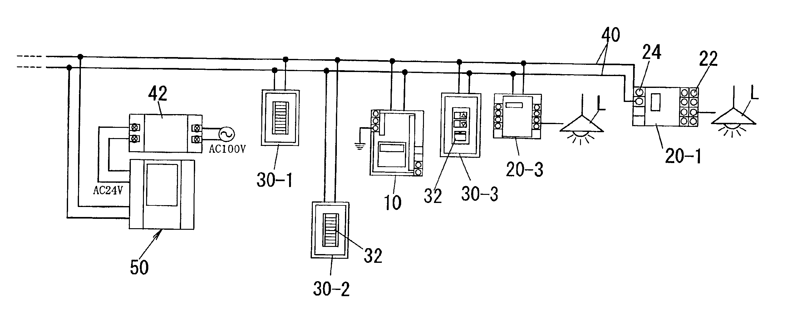
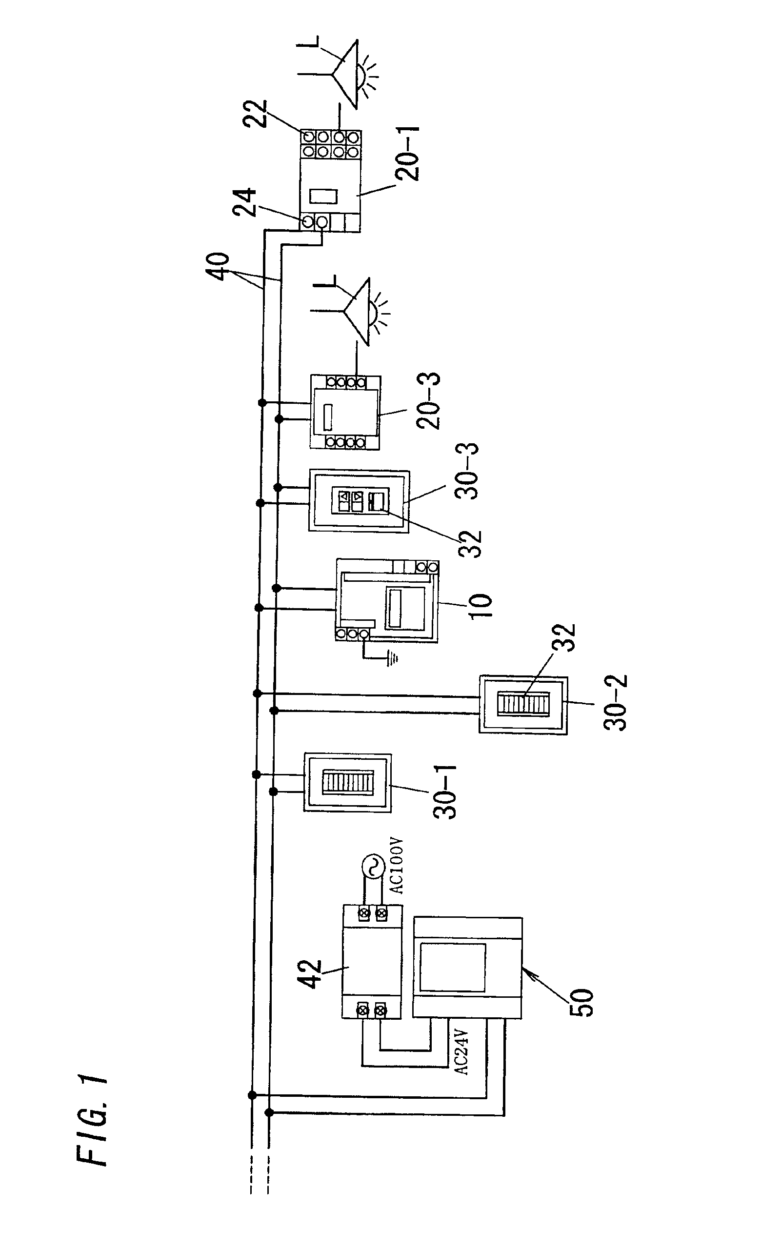
[0034]Referring to FIG. 1, there is shown a remote control load management system equipped with a programmable timer unit 50 in accordance with a preferred embodiment of the present invention. The timer unit is added to the system for controlling loads, for instance, illumination loads or lamps L according to a user's defined time schedule. Basically, the system includes a central controller 10, a plurality of load terminals 20-1 and 20-3, and a plurality of switch terminals 30-1, 30-2, 30-3 which are connected for intercommunication with each other through a two-wire transmission line 40. The load terminals 20-1 and 20-3 include two types, one 20-1 being a normal type for turning on and off the lamps, and the other 20-3 being a dimmer type capable of dimming the lamps L.

[0035]Each of the load terminals 20-1 and 20-3 is provided with load ports 22 for connection with up to four lamps L and with a line port 24 for connection with the transmission line 40. Each load terminal includes ...


PUM


Abstract

An improved programmable timer unit can be incorporated into a remote control management system to actuate loads according a user's defined schedule without relying upon any additional supplementary device for data communication. The timer unit includes an input section for selecting a switch address of any switch employed in the system and a schedule specifying the actuation time and the control code for actuation of the target load or loads. A processor makes up a load management program based upon the schedule and executes the program for control of loads. Thus, the timer unit can alone emulate any one of the switches for controlling loads without relying on additional external device for the data communication.

Description

BACKGROUND OF THE INVENTION[0001]1. Field of the Invention[0002]The present invention relates to a programmable timer unit for use in a remote control load management system, such as for controlling the illumination loads according to a user's defined pattern or schedule.[0003]2. Description of the Prior Art[0004]A remote control load management system is widely utilized in the art for controlling the illumination loads. One such typical prior art system is shown in Japanese Patent Publication No. 2-144604, which is arranged to control the illumination loads connected to a common transmission line, and includes a programmable timer unit in order to turn on and off the illumination loads according to the user's defined schedule. The system basically includes a central controller, a switch terminal, and a load terminal that are connected with each other over the transmission line for a time-division multiplexing signal intercommunication therebetween. The switch terminal is equipped w...

Claims


Application Information

Patent Timeline
Patent Type & Authority Patents(United States)
IPC IPC(8): H05B37/02H04Q9/00
CPCH05B37/0263H05B37/0281Y02B20/42H05B47/16H05B47/185Y02B20/40H04Q9/00
Inventor YOSHIMURA, YUICHITOKIZANE, TOSHIAKIYOKOTA, KOUJI
Owner MATSUSHITA ELECTRIC WORKS LTD
Why Eureka
Try Eureka