Process for making laminating preformed muntin bars

a technology of muntin bars and laminating, applied in the field of muntin bars, can solve the problems of high labor intensity, large time consumption, and significant additional cost to the final assembled product, and achieve the effect of saving time and cos

Inactive Publication Date: 2005-05-10
GED INTEGRATED SOLUTIONS
View PDF15 Cites 39 Cited by
  • Summary
  • Abstract
  • Description
  • Claims
  • Application Information

AI Technical Summary

Benefits of technology

[0013]Practice of the invention allows the laminated muntin bars to be produced on an as needed basis. A coil of strip that has been painted and treated with a second color on one half of its surface is then stored in inventory. This inventory is bent by rollforming equipment and then coated with a covering material on an as needed basis. This is to contrasted with a prior art process of fabricating muntin bars which must be shipped to a supplier and secondly shipped back to the window fabricator for inclusion in an IGU. There is a cost savings as well as a savings in time especially where the inventory is maintained at the same location that the muntin bar fabrication occurs.

Problems solved by technology

Constructing muntin bar grids for insulating glass units has been a labor intensive process.
As a consequence, manufacturing such units, and thus windows formed by the units, has been costly and inefficient.
Use of multiple steps performed by multiple suppliers results in significant additional cost to the final assembled product.
The current methods require post painting and / or lamination which are time consuming, costly and provide limited throughput.

Method used


Image

  • Process for making laminating preformed muntin bars
  • Process for making laminating preformed muntin bars
  • Process for making laminating preformed muntin bars

Examples


Embodiment Construction

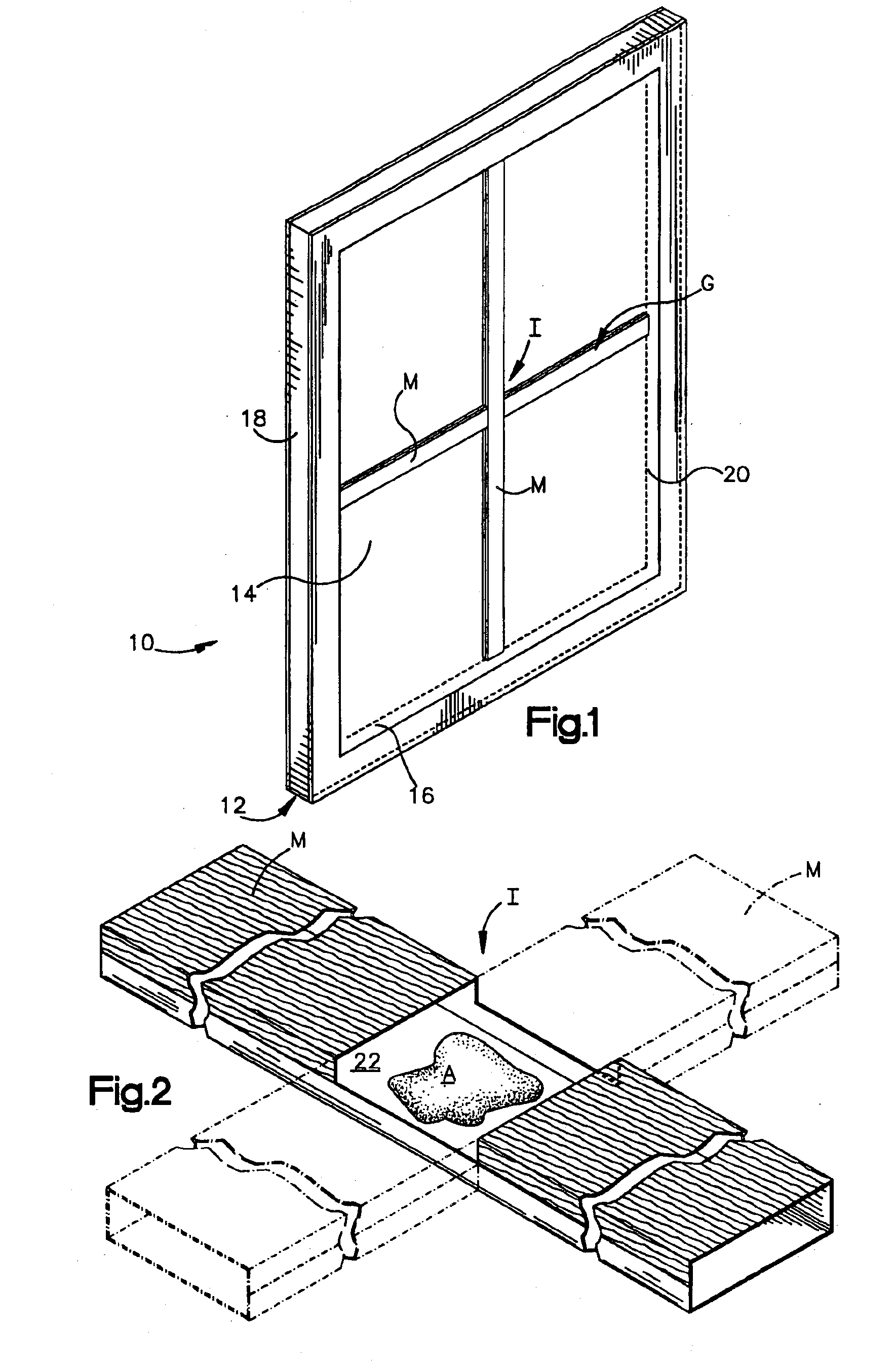
[0025]FIG. 1 shows an insulating glass unit indicated generally by the reference numeral 10 comprising a spacer assembly 12 sandwiched between glass sheets, or lights 14. The spacer assembly 12 includes a frame assembly 16 hermetically joined to the glass lights by a sealant 18 to form a closed dead air space 20 between the lights. The unit 10 is illustrated in FIG. 1 is in condition for assembly into a window or door frame (not shown).

[0026]A muntin bar grid indicated at G is disposed between the glass lights to provide the unit 10 with the appearance of a multi-pane window. As seen in FIG. 2, the illustrated grid G is comprised of muntin bars M having mating notches 22 interfitted at an intersection I. In certain instances the bars M are secured together by a suitable adhesive indicated at A, but a more common technique secures together two muntin bars with a flexible cross shaped clip that extends a short distance into each of the two intersecting muntin bars M. The ends of the m...


PUM

PropertyMeasurementUnit
lengthaaaaaaaaaa
pressureaaaaaaaaaa
heataaaaaaaaaa

Abstract

An exemplary embodiment of the invention concerns a process for forming two tone muntin bars. Method and apparatus of the invention uses an elongated preformed muntin bar member that has a treated portion of an exposed surface of the muntin bar member. An elongated strip of covering material is provided for controlled application onto a specified portion of the treated portion of the muntin bar material. The elongated strip of covering material includes an adhesive that causes the covering material to adhere to the muntin bar member. The muntin bar member and the covering material are brought into contact with each other to cause the covering material to overlie and adhere to the muntin bar member.

Description

CROSS REFERENCE TO RELATED APPLICATIONS[0001]This is a Divisional application of application Ser. No. 10 / 133,718, filed on Apr. 26, 2002 now U.S. Pat. No. 6,745,460 which is a continuation in part of application Ser. No. 09 / 781,630, entitled “Laminated Muntin Bar Method and Apparatus” to McGlinchy and which was filed in the United States Patent and Trademark Office on Feb. 12, 2001 now U.S. Pat. No. 6,687,982.FIELD OF THE INVENTION[0002]The present invention concerns muntin bars used for separating window panes of large size into smaller size panes to enhance the appearance of a window.BACKGROUND ART[0003]Windows constructed from multiple glass panes utilized “muntins” or “muntin bars” to secure the edges of the individual glass panes within the window sash. In many windows, muntins formed distinctive grid patterns that are associated with architectural styles of buildings containing the windows.[0004]Modern windows formed by insulating glass units utilize single glass fights separa...

Claims


Application Information

Patent Timeline
Patent Type & Authority Patents(United States)
IPC IPC(8): E06B3/66E06B3/673B32B37/08B44C1/10
CPCB32B38/1841B44C1/105E06B3/6604B32B37/025Y10T156/1034B32B2311/00B32B2451/00E06B3/67321Y10T156/1712Y10T29/53048Y10T29/49826Y10T156/1028Y10T29/49904Y10T29/53039Y10T29/534Y10T29/49623Y10T29/49829Y10T29/53313Y10T29/49885Y10T29/49906B32B37/08
Inventor MCGLINCHY, TIMOTHY BRYAN
Owner GED INTEGRATED SOLUTIONS
Why Eureka
Try Eureka