
Modular wall panel construction

a technology for modular wall panels and construction, applied in the direction of walls, service system furniture, swimming pools, etc., can solve the problems of slow adjustment, difficult access to adjustability, and obscuring the stem from view

Inactive Publication Date: 2005-05-10
HNI TECH INC
View PDF16 Cites 60 Cited by
  • Summary
  • Abstract
  • Description
  • Claims
  • Application Information

AI Technical Summary

Benefits of technology

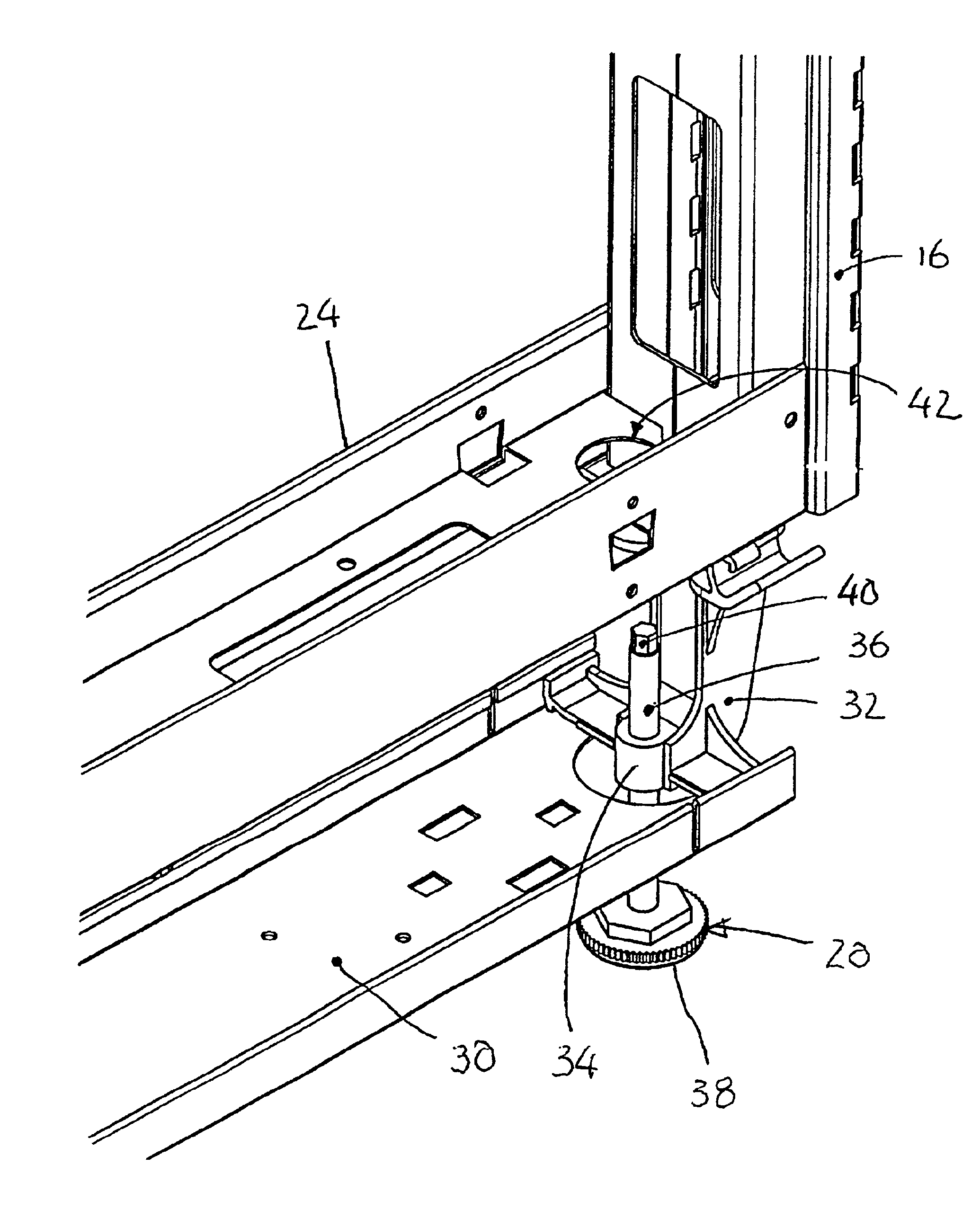
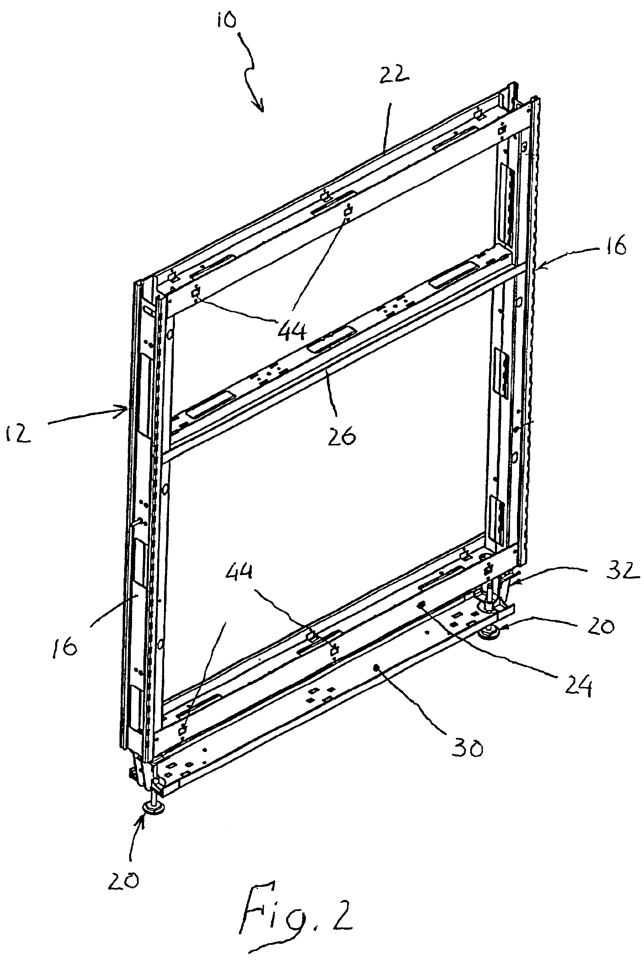
[0007]The present invention improves over the prior art by providing a modular wall panel assembly including a generally rectangular preassembled frame having a generally horizontal lower channel member and a base rail secured to the lower channel member in parallel spaced relation thereto. Two opposed floor glide assemblies are secured to the base rail and each includes an upwardly directed threaded stem configured at their upper ends to be rotated by a suitable rotary tool. An aperture is provided in the lower channel member in registry with each stem. The frame can thus be leveled on a floor by inserting a rotary tool vertically through the apertures and rotating the threaded stems as desired. Thereafter, decorative or other panels may be conveniently installed on the frame to substantially conceal the floor glides.

Problems solved by technology

However, a problem encountered with known floor glides as used on modular wall panels is that they are difficult to access for adjustability.
Typically, the usual floor glide has a threaded stem which is adjustable using a wrench from beneath the panel and is slow to adjust because the wrench can be moved only through a small range of stem rotation at a time.
Often the stem is obscured from view and the installer must rotate the stem by manual feel alone.
However, in such a system the framework of the panel must essentially be assembled in individual pieces making the panel system time consuming to construct on site.

Method used


Image

  • Modular wall panel construction
  • Modular wall panel construction
  • Modular wall panel construction

Examples


Embodiment Construction

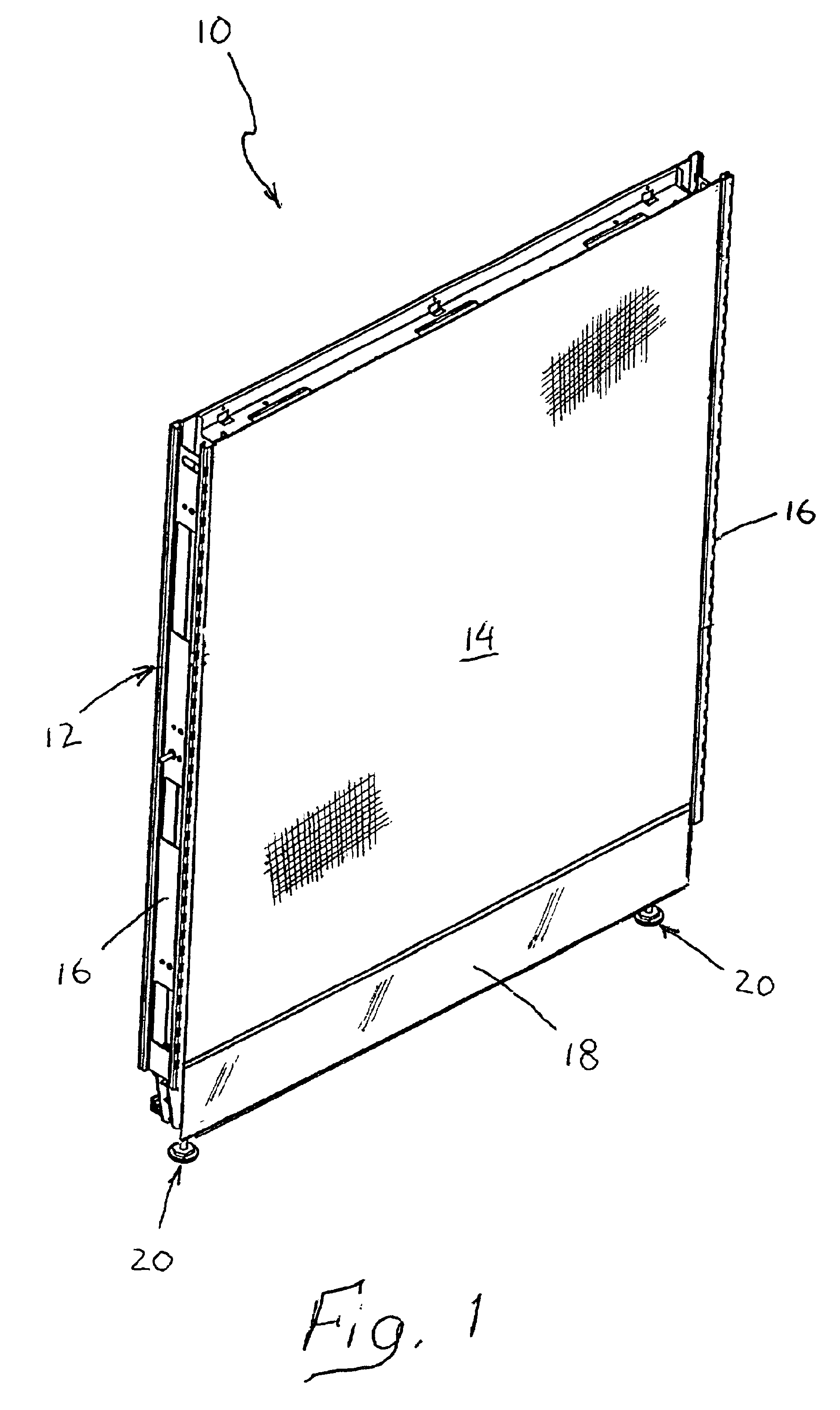
[0012]Referring now to the drawing, and initially to FIG. 1, a modular wall panel assembly is designated generally by the reference numeral 10 and includes as its principal components a generally rectangular preassembled frame 12, which will more readily be seen in detail in FIG. 2, to which an upper decorative panel 14 has been detachably secured. In a manner well-known in the art the panel 14 may be fabric covered with any desirable material for sound deadening and aesthetic appearance. The modular panel 10 is constructed as to be readily connected along side rails 16 to other similar panels to create a system of space dividing partitions suitable for an office environment. Along the bottom of the panel 10 a kick plate 18 may be detachably secured to the frame 12. A pair of floor glides 20 project downwardly from the panel 10 beneath the kick plate 18 as will be described in detail hereinafter.

[0013]Turning now to FIG. 2, the panel 10 is illustrated with the decorative panel 14 an...


PUM


Abstract

A modular wall panel assembly includes a generally rectangular preassembled frame having a generally horizontal lower channel member and a base rail secured to the lower channel member in parallel spaced relation thereto. Two opposed floor glide assemblies are secured to the base rail and each includes an upwardly directed threaded stem configured at their upper ends to be rotated by a suitable rotary tool. An aperture is provided in the lower channel member in registry with each stem. The frame can thus be leveled on a floor by inserting a rotary tool vertically through the apertures and rotating the threaded stems as desired. Thereafter, decorative or other panels may be conveniently installed on the frame to substantially conceal the floor glides.

Description

BACKGROUND OF THE INVENTION[0001]1. Field of the Invention[0002]The present invention relates generally to a method and apparatus for installing modular wall panels of the type used in office environments and, more particularly, to a method and apparatus for quickly and conveniently leveling modular wall panels during installation.[0003]2. Description of the Related Art[0004]Modular wall panel systems have become increasingly popular as a means for dividing space in modern offices. Such systems offer the advantage that space can be conveniently reconfigured as the needs of the office environment change. They can be added to, changed in space dimensions and moved with relatively little manual labor and office disruption as compared to permanent partition construction. An example of a modular wall panel system is disclosed in U.S. Pat. No. 4,685,255 issued to Kelley. A typical modular wall panel comprises a metal frame to which one or more decorative panels are attached. The decorativ...

Claims


Application Information

Patent Timeline
IPC IPC(8): E04B2/82E04C2/00E04H4/04E04H4/00E04B2/74
CPCE04B2/7422E04B2002/749
Inventor KOTTMAN, MARK A.
Owner HNI TECH INC
Learn More