Method of providing hydraulic pressure for mechanical work from an engine lubricating system

a technology of hydraulic pressure and mechanical work, which is applied in the direction of auxillary lubrication, non-mechanical valves, lighting and heating apparatus, etc., can solve the problem that the system does not provide engine lubrication

Inactive Publication Date: 2005-05-10
BORGWARNER INC
View PDF8 Cites 10 Cited by
  • Summary
  • Abstract
  • Description
  • Claims
  • Application Information

AI Technical Summary

Problems solved by technology

The loads on the system are for hydraulic pistons and not continuous flow devices (motors), and the system does not provide engine lubrication.

Method used


Image

  • Method of providing hydraulic pressure for mechanical work from an engine lubricating system
  • Method of providing hydraulic pressure for mechanical work from an engine lubricating system
  • Method of providing hydraulic pressure for mechanical work from an engine lubricating system

Examples


Embodiment Construction

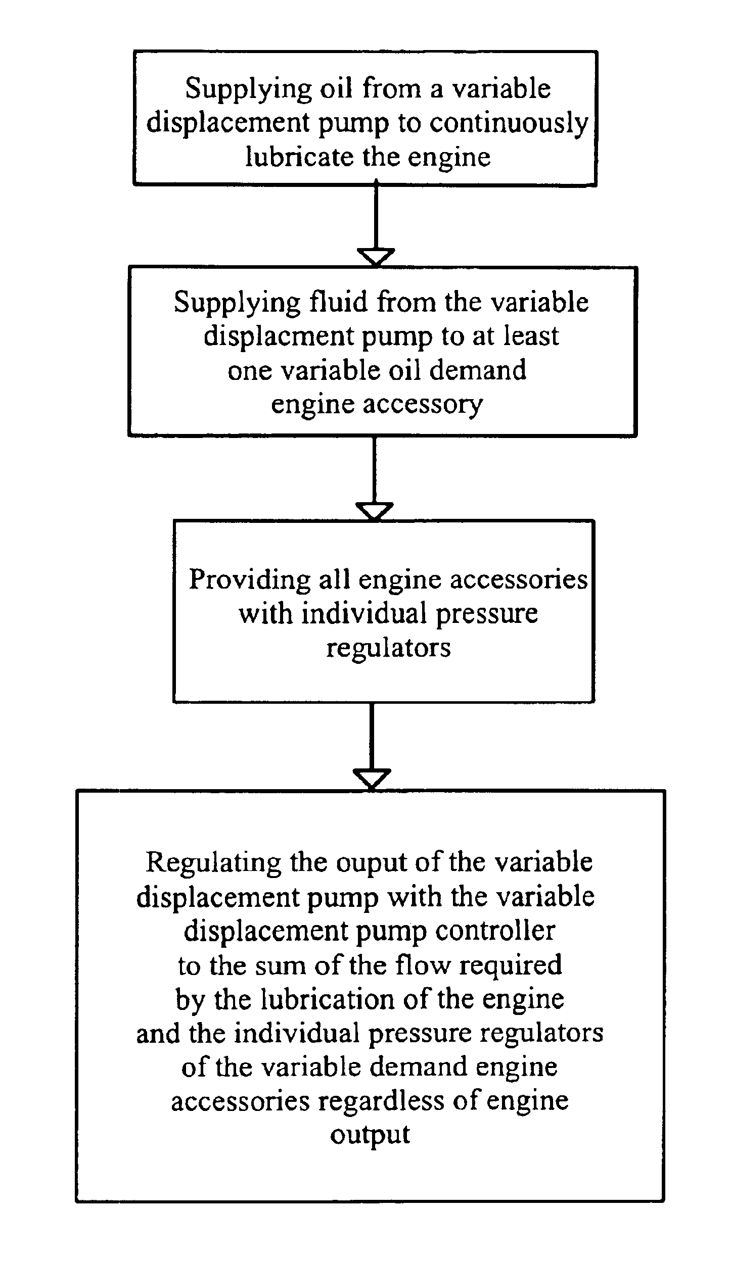
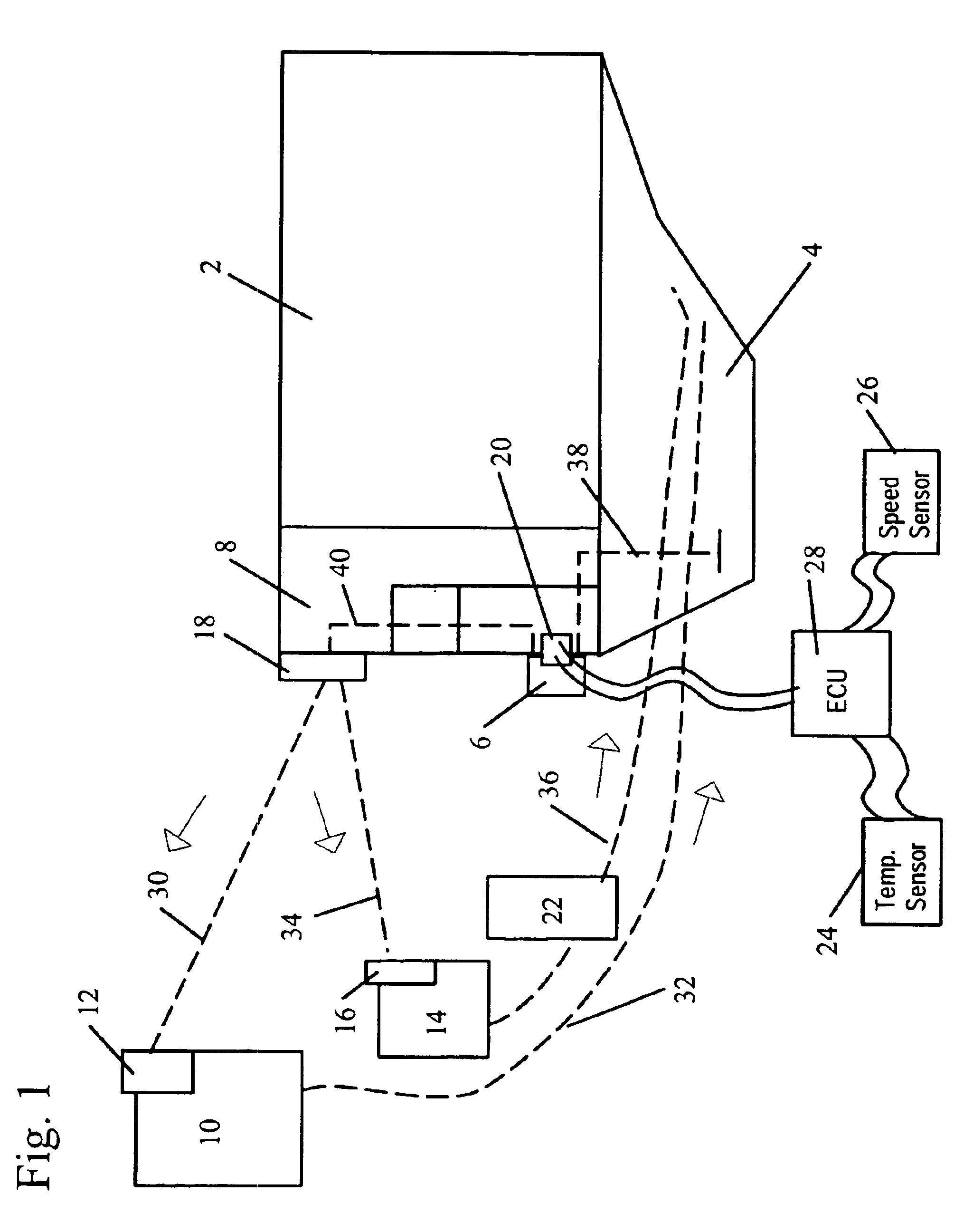
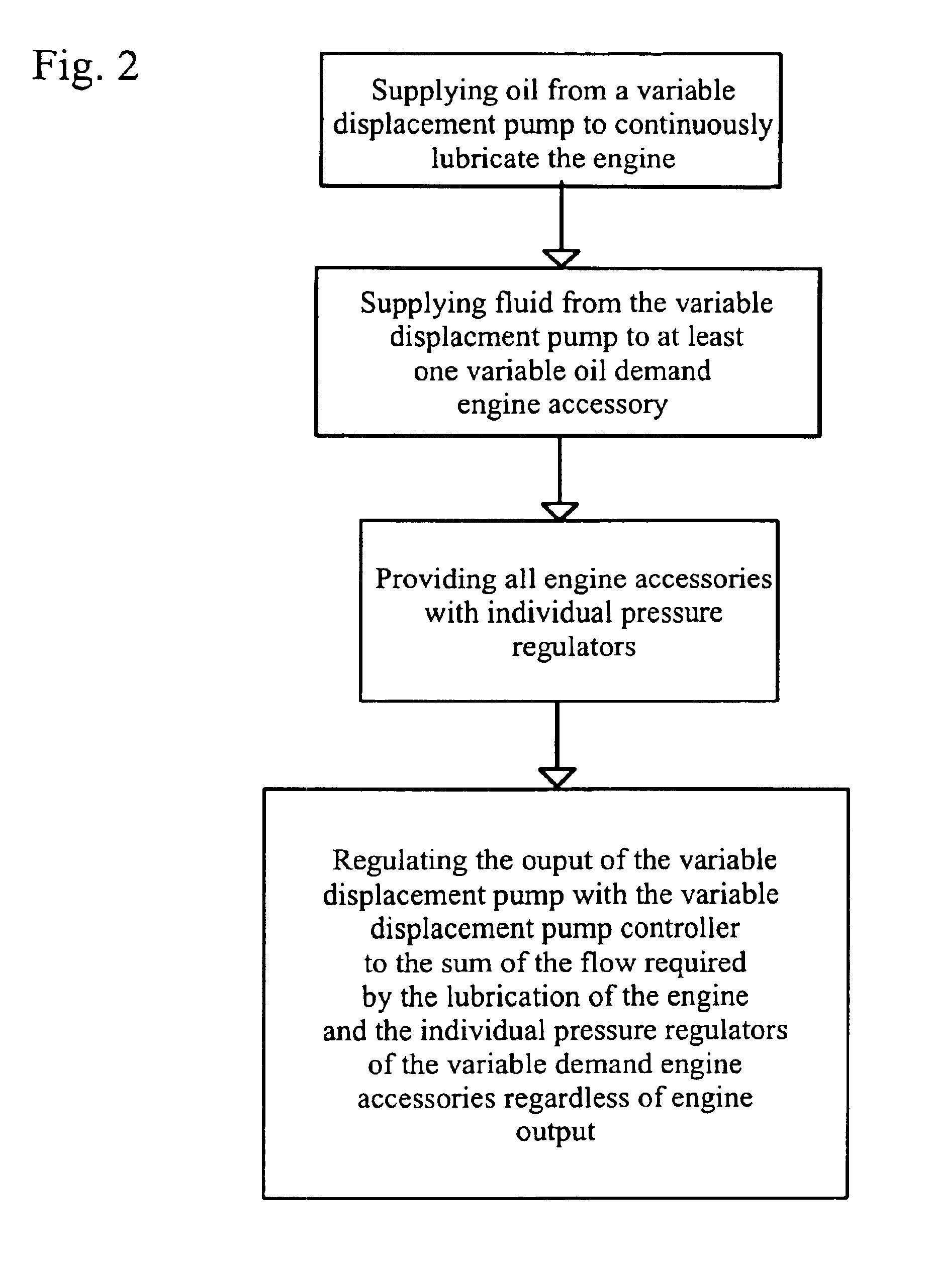
[0014]Referring to FIGS. 1 and 2, mounted to the front cover 8 of the engine block 2 is a variable displacement pump 6 and the variable displacement pump controller 20. Below engine block 2 is a sump or oil pan 4. Also connected to the front cover 8 of the engine block 2 is the high pressure manifold 18.

[0015]The variable displacement pump 6 is driven by a conventional valve chain, gear, or belt (not shown). Line 38 connects the variable displacement pump 6 to the sump 4. Line 40 passes though the front cover 8 of the engine block 2 and connects the variable displacement pump 6 to the high pressure manifold 18. The high pressure manifold 18 may be incorporated into the front cover or be a completely separate and external. The variable displacement pump 6 is regulated by the variable displacement pump controller 20 to the sum of fluid or oil required by lubrication of the engine and the fluid demanded by the variable on-demand engine accessories 10, 14. The controller 20 receives inp...


PUM


Abstract

A method of providing hydraulic pressure for mechanical work from an engine lubricating system in an internal combustion engine by supplying oil to an engine lubrication gallery for lubricating the engine and at least one variable oil demand accessory. Each of the variable oil demand accessories have individual pressure regulators. The output of the variable displacement pump is regulated to the sum of fluid flow required by the engine lubricating system and the demand for fluid generated by the individual pressure regulators on each of the engine accessories, regardless of the engine output.

Description

BACKGROUND OF THE INVENTION[0001]1. Field of the Invention[0002]The invention pertains to the field of engine lubricating systems. More particularly, the invention pertains to a method of providing hydraulic pressure for mechanical work from an engine lubricating system.[0003]2. Description of Related Art[0004]Conventionally, accessories in cars, (i.e. cooling fan, power steering system, A / C compressor, engine coolant pump, supercharger, and alternator) are powered using separate engine driven, fixed displacement pumps, or by direct drive, where the individual power demands of the accessories are not well matched to engine speed.[0005]Solutions to the allocation of power by accessories is shown in U.S. Pat. No. 3,952,509, U.S. Pat. No. 4,420,937, U.S. Pat. No. 4,819,430, U.S. Pat. No. 5,800,131 and U.S. Pat. No. 6,644,025.[0006]In U.S. Pat. No. 3,952,509 a variable displacement pump supplies hydraulic fluid to continuous and intermittent output hydraulic circuits. The continuous cir...

Claims


Application Information

Patent Timeline
Patent Type & Authority Patents(United States)
IPC IPC(8): F01M1/02F01M11/02
CPCF01M1/02F01M2011/021
Inventor ROTH, DAVID B.
Owner BORGWARNER INC
Why Eureka
Try Eureka