
Steerable parachute control system and method

a control system and parachute technology, applied in the field of unmanned parachutes, to achieve the effect of improving performance, high speed and great control

Inactive Publication Date: 2005-05-10
ATAIR AEROSPACE +1
View PDF8 Cites 56 Cited by
  • Summary
  • Abstract
  • Description
  • Claims
  • Application Information

AI Technical Summary

Benefits of technology

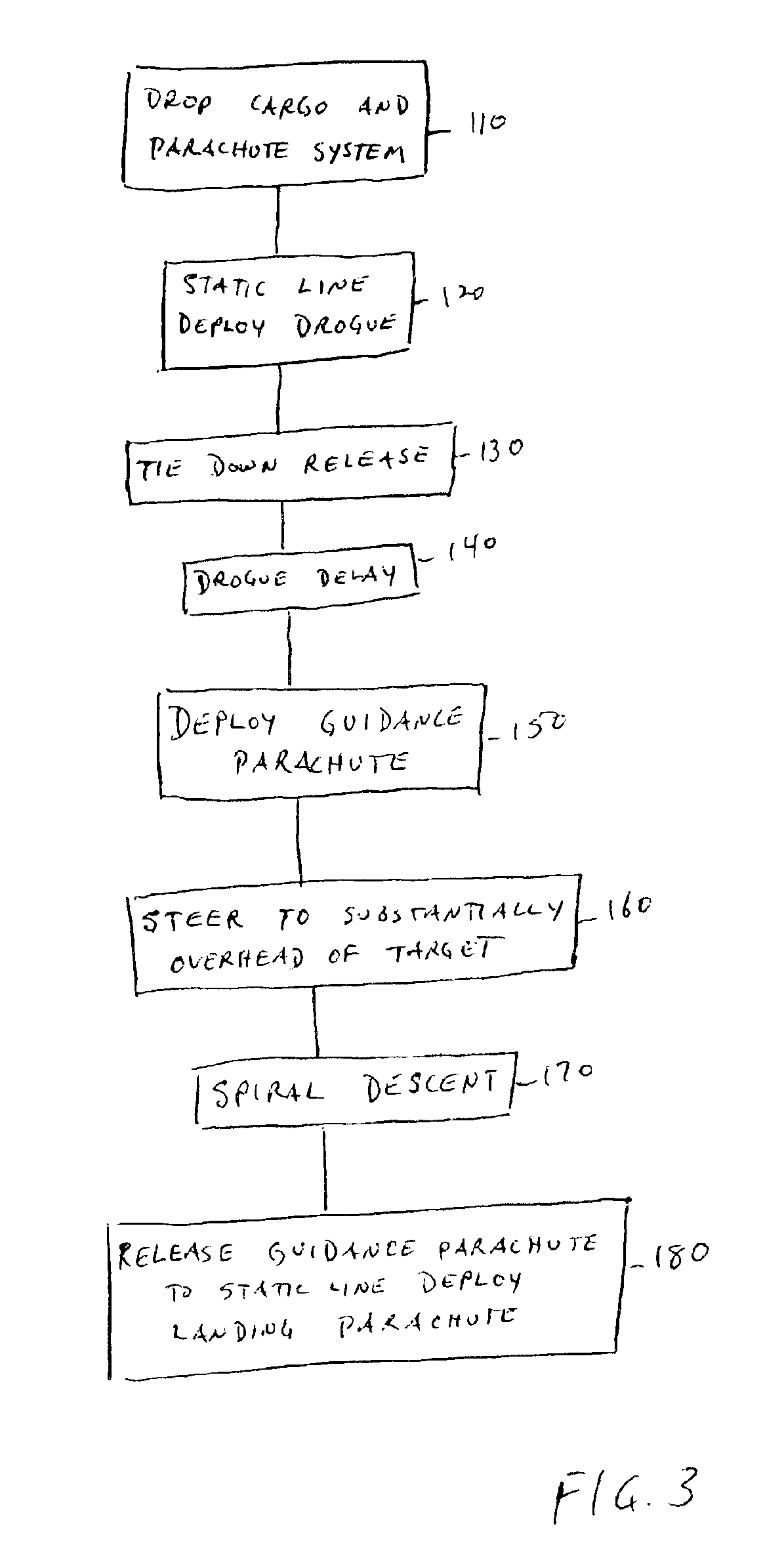
[0011]The deficiencies of the prior art are substantially overcome by the guided, multi-stage parachute system of the present invention. According to an aspect of the invention, the parachute system includes two different kinds of parachutes for use during different phases of the cargo drop process. The requirements of guidance and soft landing have been separated. A fast, high performance ram air parachute is used to guide the cargo in substantially a straight line from exit point to substantially overhead of the target location and then rapidly spiral dive down to lose altitude. The system transitions to a larger unguided landing parachute prior to impact. The multi-stage parachute system utilizes the advantages of different kinds of parachutes to achieve greater control and improved performance. Since the gliding parachute is not used for landing of the cargo, it can be designed for extremely high speed and high wing load capabilities. These features allow higher reliability in high altitude drops by limiting the effect of winds and greatly reduce time aloft. Since the landing parachute is not used to control location, it can be designed for a soft landing of large cargos. Also, it can be deployed at the lowest possible altitudes to minimize unguided drift.

Problems solved by technology

The time delay may be a mechanical delay or may be controlled by the flight controller.

Method used


Image

  • Steerable parachute control system and method
  • Steerable parachute control system and method
  • Steerable parachute control system and method

Examples


Embodiment Construction

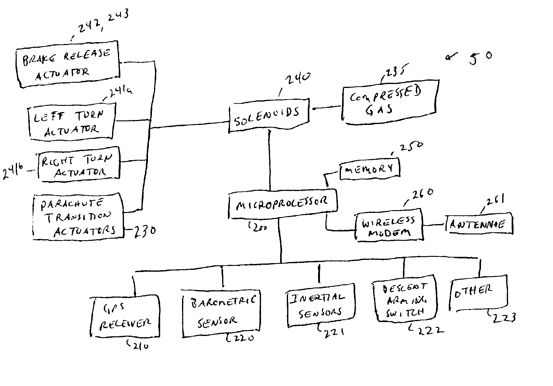
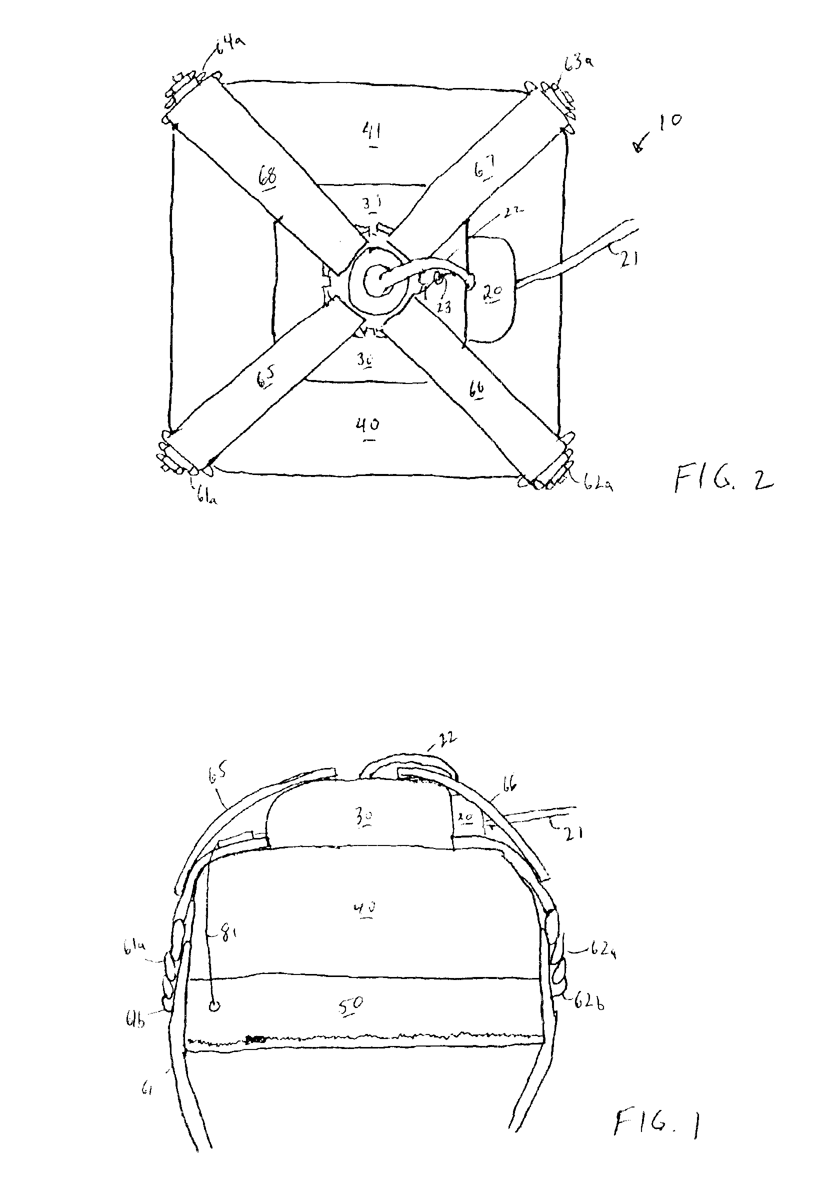
[0026]In order to provide improved performance for automatic control of cargo drops, the parachute system of the present invention includes multiple parachutes and a flight controller. FIGS. 1 and 2 are respectively a side view and a top view of an embodiment of the parachute system 10 of the present invention when packed for deployment. The parachute system includes a drogue 20, a high wing loaded, guidance parachute or wing 30, and a landing parachute 40. Preferably, the guidance parachute is a high wing loaded, high speed, steerable, ram air parachute. However, any controllable wing or parachute may be used. Preferably, the landing parachute is a larger parachute allowing slow unguided vertical descent. A flight controller 50 is disposed below the parachutes and operates to control deployment of the parachutes and steering of the guidance parachute. The parachutes 20, 30, 40 may be of any known design based upon the type of chute required for the specific operation.

[0027]FIG. 3 i...


PUM


Abstract

An autonomous guided parachute system for cargo drops that divides the requirements of guidance and soft landing into separate parachutes. Said invention includes a high wing-loaded ram air parachute for guidance, a larger round parachute for soft landing, a harness / container system, flight computer, position sensors and actuation system. The system is dropped from an airplane. A predetermined period of drogue fall ensures a stable position prior to deploying the guidance parachute. The flight controller determines a heading to intersect with an area substantially above the desired target and controls the guidance parachute via pneumatic actuators connected to the parachutes steering lines to fly on that heading. At a minimum altitude prior to the system's impact with the ground the flight computer transitions the system from the fast high performance guidance parachute to a larger landing parachute by releasing the guidance parachute to static line extract and deploy the landing parachute. If the system reaches a position substantially above target area prior to the parachute transition altitude the flight computer controls the system into a spiral dive or other rapid altitude dropping maneuver until the transition altitude is reached. Once transitioned to the landing parachute the system descends for a brief period unguided under the landing parachute until touchdown.

Description

[0001]This application claims priority to U.S. Provisional Application Ser. No. 60 / 341,006 filed Dec. 7, 2001.BACKGROUND OF THE INVENTION[0002]1. Field of the Invention[0003]The invention relates generally to unmanned parachutes for cargo drops. More particularly, it relates to a control system and method for targeted landing of cargo using controllable parachutes.[0004]2. Discussion of Related Art[0005]Parachutes have evolved over the years into highly sophisticated systems, and often include features that improve the safety, maneuverability, and overall reliability of the parachutes. Initially, parachutes included a round canopy. A skydiver was connected to the canopy via a harness / container to suspension lines disposed around the periphery of the canopy. Such parachutes severely lacked control. The user was driven about by winds without any mechanism for altering direction. Furthermore, such parachutes had a single descent rate based upon the size of the canopy and the weight of ...

Claims


Application Information

Patent Timeline
IPC IPC(8): B64D1/00B64D17/34B64D17/00B64D17/04B64D17/08B64D17/54B64D1/14B64D17/38B64D17/02
CPCB64D1/14B64D17/025B64D17/04B64D17/08B64D17/34G05D1/105B64D17/54B64D17/74F42B4/28F42B10/56F42B10/58B64D17/38B64D1/08
Inventor PRESTON, DANIEL
Owner ATAIR AEROSPACE
Learn More