Independently rotating wheels

a technology of independent rotating wheels and axles, applied in mechanical equipment, sliding contact bearings, transportation and packaging, etc., can solve the problems of tire wear, tire wear, tire wear and maintenance of heavy-duty off-highway vehicles due to scrubbers, thousands of dollars annually per vehicle, etc., and achieve the effect of reducing tire wear

Inactive Publication Date: 2005-05-10
AXLETECH INT IP HLDG
View PDF74 Cites 12 Cited by
  • Summary
  • Abstract
  • Description
  • Claims
  • Application Information

AI Technical Summary

Benefits of technology

[0005]A wheel end assembly having a dual wheel configuration includes independently rotating wheel hubs to reduce tire wear. In a disclosed embodiment of this invention, the wheel end assembly includes a spindle defining an axis of rotation a first wheel hub supported on the spindle by a first bearing member and a second wheel hub supported on the spindle by a second bearing member for rotation about the axis. A third bearing member is mounted between the first and second wheel hubs to support and permit the first and second wheel hubs to rotate independently from each other under predetermined conditions. In straight path operation the wheel hubs rotate together at the same speed, but during turns the third bearing member allows each wheel hub to turn at an ideal speed for that respective wheel hub.
[0008]The subject invention offers a simple and compact design for independently rotating wheel hubs that significantly reduces tire wear resulting in less vehicle down time and which decreases overall maintenance cost. Further, because tire scrub is eliminated vehicle stability is improved and fuel economy is improved. The subject invention, described above for a dual wheel configuration, can easily be extended to multiple-wheel configurations.

Problems solved by technology

Most off-highway vehicles, such as lift trucks, container handlers, front end loaders, etc., have duty cycles that include numerous turning maneuvers, which cause significant tire wear.
The tire wear is a direct result of tire scrub, or drag, caused by wheels that are rigidly secured together for rotation at the same speed but which must travel different distances at the inside and outside of the turning radius.
Tire wear and maintenance on heavy duty off-highway vehicles due to scrub cost thousands of dollars annually per vehicle.
Additionally, tire scrub reduces vehicle stability during turning maneuvers.
Tire scrub also causes premature wear of various wheel end components, such as wheel rims.
The wheel rims can fail prematurely due to added stresses caused by repeated tire scrub.
Finally, tire scrub increases fuel consumption as well as powertrain wear and tear in drive axles.

Method used


Image

  • Independently rotating wheels
  • Independently rotating wheels
  • Independently rotating wheels

Examples


Embodiment Construction

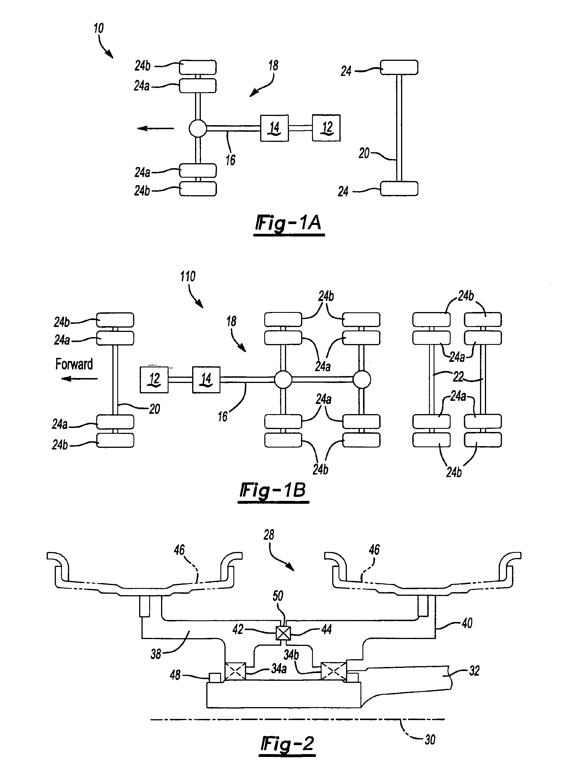
[0019]FIG. 1A shows an overhead schematic view of a typical vehicle driveline 10 for a heavy-duty off-highway vehicle. FIG 1B shows a typical on-highway vehicle driveline 110. The drivelines 10, 110 include an engine 12 coupled to a transmission 14, which together provide driving input torque to a drive shaft 16 that extends to a drive axle 18. The drive axle 18 can be a single drive axle or a tandem drive axle. The vehicle also typically includes non-driving axles such as a front non-drive steer axle 20 and in the on-highway configuration, trailer axles 22.

[0020]Typically each axle 18, 20, 22 includes a wheel end assembly with dual wheels 24a, 24b on either end of the respective axle to increase the load bearing capacity for the heavy duty vehicle. As the vehicle maneuvers through a turn, the outer wheel 24b on the wheel end on the outside of the turn has a greater distance to travel than the inner wheel 24a. Conversely, on the inside of the turn, the inner wheel 24a travels farthe...


PUM


Abstract

A wheel end assembly having a dual wheel configuration includes independently rotating wheel hubs to reduce tire wear. Each wheel hub is supported on an axle spindle via a bearing member. Another bearing member is mounted between the wheel hubs to allow each wheel hub to rotate independently from the other. A fastening assembly retains the hubs on the spindle to prevent linear movement along the spindle.

Description

BACKGROUND OF THE INVENTION[0001]This invention relates to an axle assembly having multiple wheels at each end of the axle in which one wheel on one axle end is permitted to rotate relative to the other wheels on the same axle end. More specifically, the invention relates to bearing members that support adjacent wheel hubs to achieve independent relative rotation during turns.[0002]Axle assemblies have typically incorporated dual wheels on either end of the axle to increase the load bearing capacity for heavy duty vehicles. Typically the pair of wheels on each end of the axle assembly is secured together so that they rotate at the same speed about an axis even during turns. Most off-highway vehicles, such as lift trucks, container handlers, front end loaders, etc., have duty cycles that include numerous turning maneuvers, which cause significant tire wear. The tire wear is a direct result of tire scrub, or drag, caused by wheels that are rigidly secured together for rotation at the ...

Claims


Application Information

Patent Timeline
Patent Type & Authority Patents(United States)
IPC IPC(8): B60B11/00B60B37/00B60B37/10B60B11/02F16C17/10F16C19/16F16C19/18F16C19/38F16C33/12F16C33/20
CPCB60B37/10B60B11/00F16C19/386
Inventor CHUNG, I-CHAO
Owner AXLETECH INT IP HLDG
Why Eureka
Try Eureka