Floatable panel mount cable assembly

Inactive Publication Date: 2005-05-10
HON HAI PRECISION IND CO LTD
View PDF3 Cites 32 Cited by
  • Summary
  • Abstract
  • Description
  • Claims
  • Application Information

AI Technical Summary

Benefits of technology

[0009]Accordingly, an object of the present invention is to provide a floatable panel mount cable assembly which can be preve

Problems solved by technology

However, this design is complicated and increases the manufacturing cost.
Further, when the female connector engages with or disengages from the male connector, the male connect

Method used


Image

  • Floatable panel mount cable assembly
  • Floatable panel mount cable assembly
  • Floatable panel mount cable assembly

Examples


Example

[0021]Reference will now be made in detail to the preferred embodiment of the present invention.

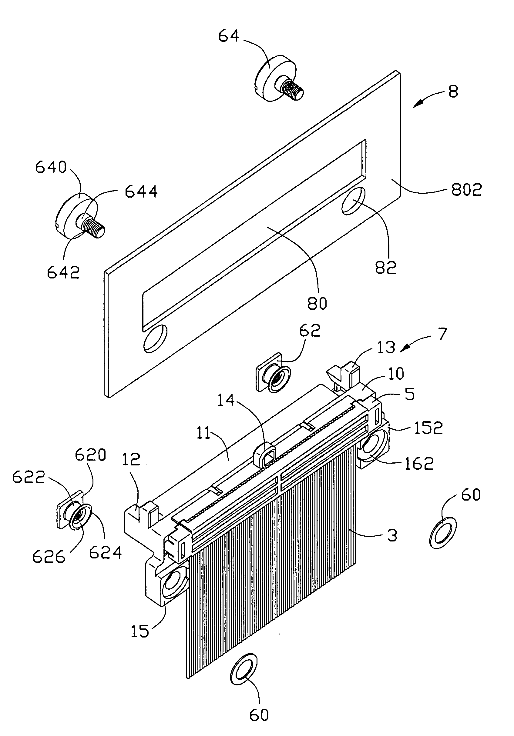
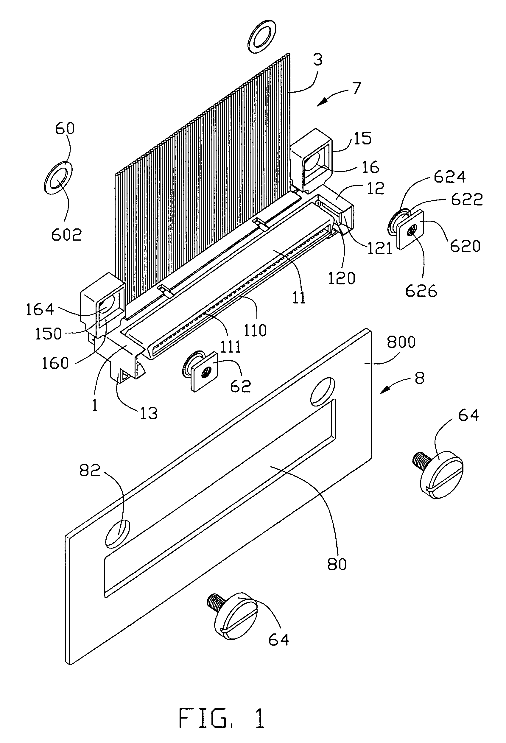
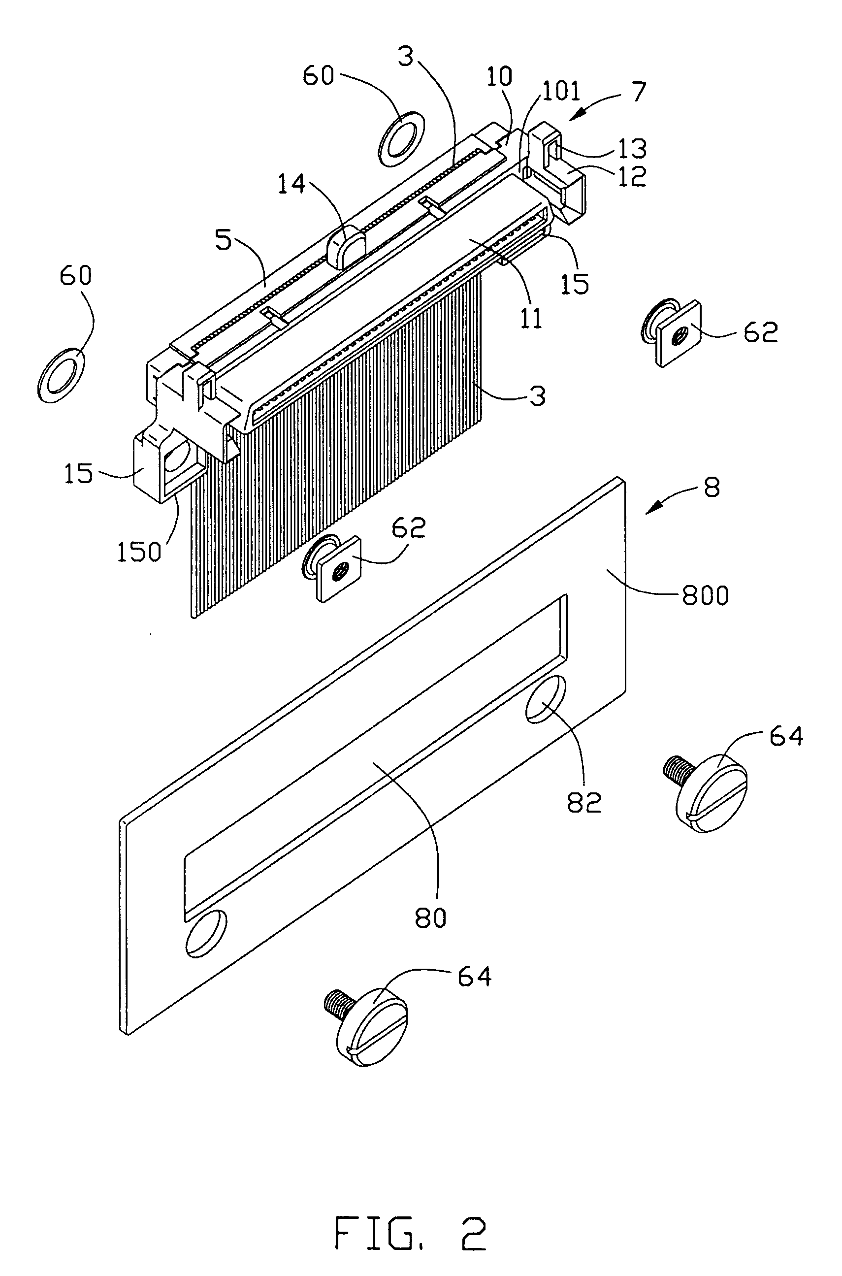
[0022]Referring to FIGS. 1–3 and 7–9, a cable assembly 7 in accordance with the present invention, which is float-mounted on a panel 8 via a pair of fastening devices 6, comprises an insulative housing 1, a plurality of IDC (Insulation Displacement Contact) terminals 2 received in the insulative housing 1, a multi-conductor flat cable 3 electrically connecting with the terminals 2, a spacer 4 assembled to the insulative housing 1 for positioning insulation displacement sections of the terminals 2 and a termination cover 5 for being latchably mounted on the insulative housing 1. In a preferred embodiment, the cable assembly 7 is a SCA (Single Connector Attachment) cable assembly.

[0023]The insulative housing 1 is substantially elongated and comprises a base 10 and a mating portion 11 extending perpendicularly and forwardly from a front face 101 of the base 10. The insulative housing 1 has a...


PUM


Abstract

A cable assembly (7) includes an insulative housing (1) and a number of contacts (2) received in the insulative housing. The cable assembly includes a base (10) along a longitudinal direction thereof, a mating portion (11) extending forwardly from a front face (101) of the base along a mating direction perpendicular to the longitudinal direction, and a pair of mounting ears (15) integrally formed at opposite ends of the base. A bulge (14) and at least one projection (13) are formed on the housing adjacent the front face of the base for engaging with a first face and an opposite second face of a panel, respectively.

Description

CROSS-REFERENCE TO RELATED APPLICATIONS[0001]Relevant subject matter is disclosed in U.S. patent application Ser. Nos. 10 / 658,563 filed on Sep. 8, 2003 and entitled “ELECTRICAL CONNECTOR ASSEMBLY WITH BLIND MATE STRUCTURE”, 10 / 665,843 filed on Sep. 18, 2003 and entitled “SPACE-SAVING CABLE CONNECTOR ASSEMBLY WITH BLIND MATE STRUCTURE” and 10 / 671,117 filed on Sep. 24, 2003 and entitled “CABLE CONNECTOR ASSEMBLY”, all of which are invented by the same inventor and assigned to the same assignee as this application.BACKGROUND OF THE INVENTION[0002]1. Field of the Invention[0003]The present invention relates to a cable assembly, and particularly to a floatable panel mount cable assembly.[0004]2. Description of Related Art[0005]Cable assemblies are widely used in electronic devices for signal or power transmission. Such a cable assembly is usually needed to be float-mounted to a panel on which plural connectors are arranged side by side to form a sub module. U.S. Pat. Nos. 4,647,130 and 4...

Claims


Application Information

Patent Timeline
IPC IPC(8): H01R13/631H01R13/74
CPCH01R13/6315H01R12/675H01R13/748
Inventor WU, JERRY
Owner HON HAI PRECISION IND CO LTD
Why Eureka
Try Eureka