Continuous liquid infusion device

a technology of continuous liquid and infusion device, which is applied in the direction of medical devices, intravenous devices, medical devices, etc., can solve the problems of poor operationability and difficulty in precise manufacturing, and achieve the effect of excellent continuous liquid infusion function, reduced number of parts, and easy creation of extra vacuum parts

Inactive Publication Date: 2005-05-10
ORCHIS
View PDF16 Cites 7 Cited by
  • Summary
  • Abstract
  • Description
  • Claims
  • Application Information

AI Technical Summary

Benefits of technology

[0010]In order to achieve the objects described above, the continuous liquid infusion device according to the present invention is characterized in that it comprises: a negative pressure cylinder having a barrel part with an open/close valve at its tip and leg parts extending from a base end of the barrel part; a piston air-tightly fitted in the barrel part of the negative pressure cylinder and connected to a base end of an outer case, which covers an outer surface of the barrel part, through slots between the leg parts of the negative pressure cylinder; a liquid syringe having a base end screwed with the outer case so that the liquid syringe is positioned back to back with the negative pressure cylinder, and a liquid infusion/discharge port at its tip; and a movable unit liquid-tightly fitted to an inner circumference of the tip of the liquid syringe and abutting against a base end of the leg parts of the negative pressure cylinder. In the continuous liquid infusion device the negative pressure cylinder moves by screwing the outer case to easily create an extra vacuum part (a spare pressure part for completely infusing liquid in the liquid sy

Problems solved by technology

The conventional continuous liquid infusion device as described above requires two positions having large sliding resistance in the cylinder and the syringe in order to maintain air-tightnes

Method used


Image

  • Continuous liquid infusion device
  • Continuous liquid infusion device
  • Continuous liquid infusion device

Examples


Embodiment Construction

[0025]Next, an embodiment of the present invention will be explained with reference to the attached drawings.

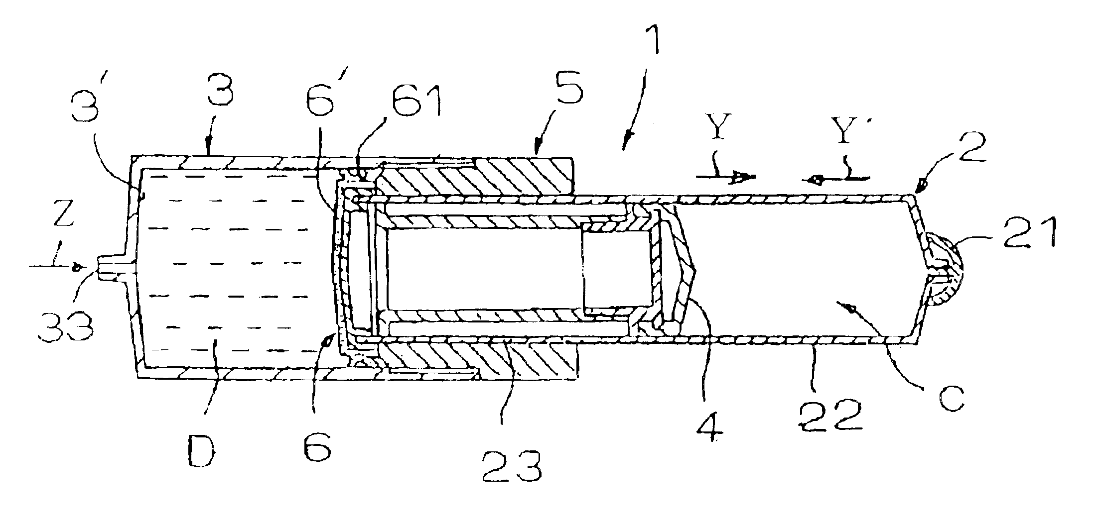
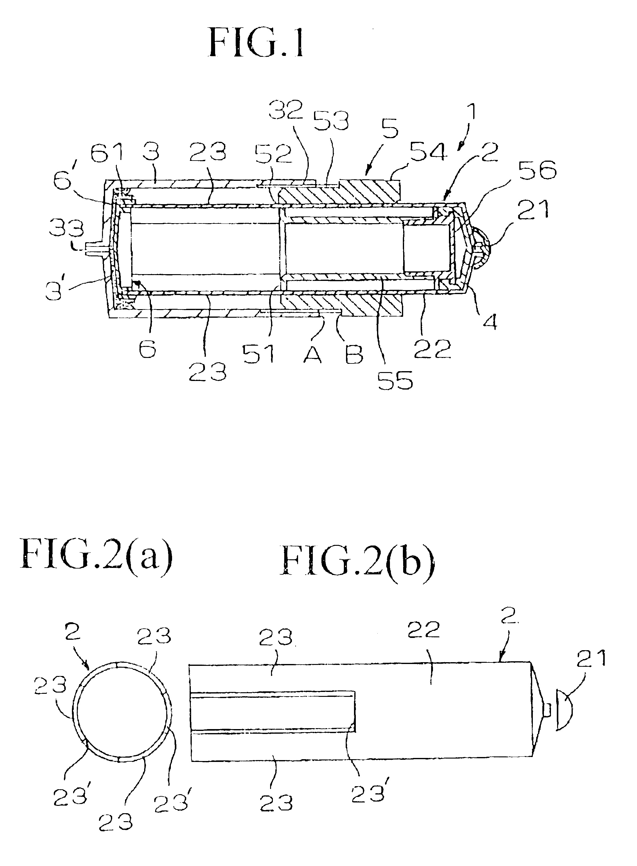
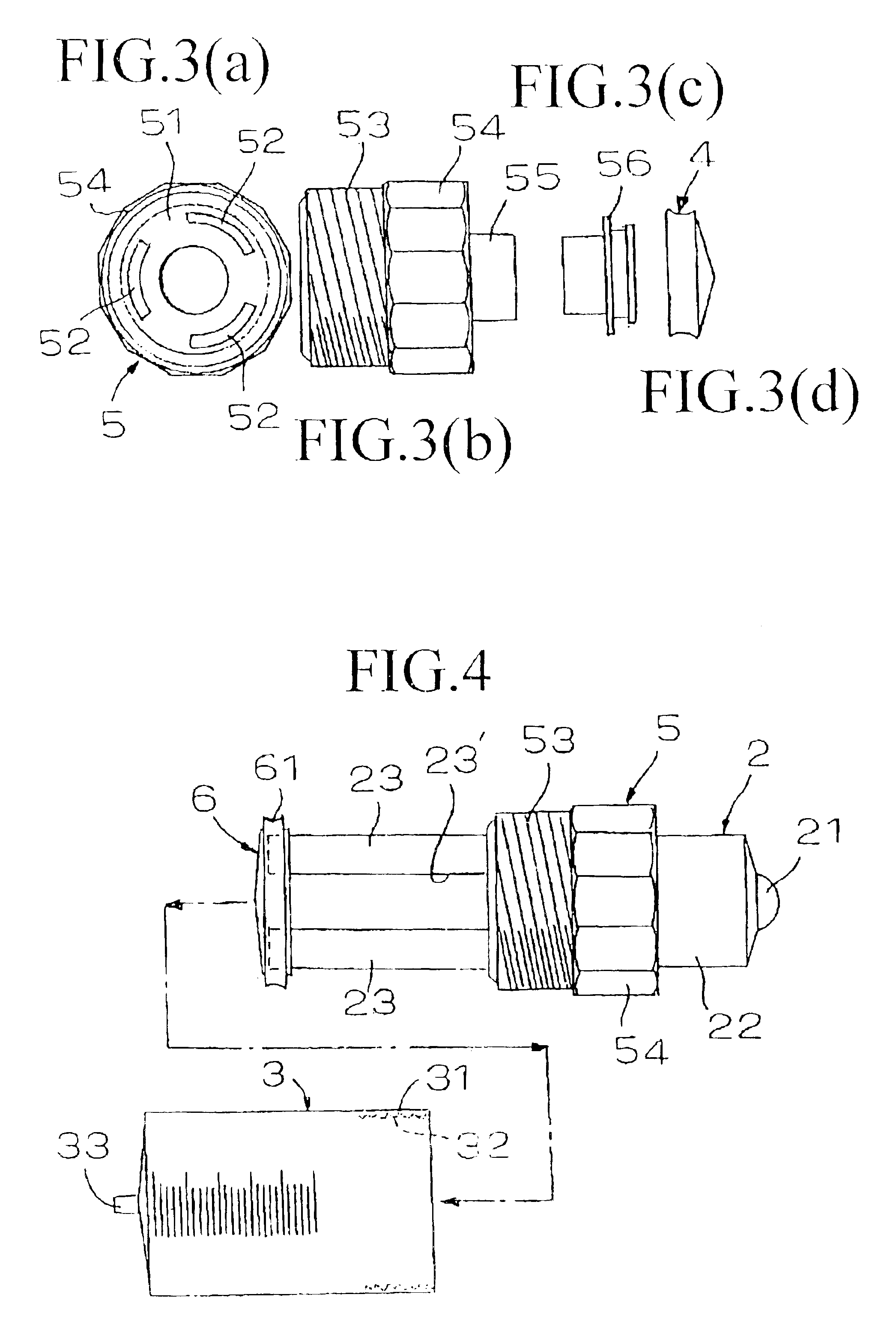
[0026]In the drawings, a continuous liquid infusion device according to one embodiment of the present invention is referenced to as number 1. In the continuous liquid infusion device 1, a negative pressure cylinder 2 and a liquid syringe 3 are positioned back to back. As shown in FIGS. 2(a) and 2(b), the negative pressure cylinder 2 has a barrel part 22 having an open / close valve 21 at its tip and leg parts 23 extending from a base end thereof. The base end of the barrel part 22 is equally divided into three (not limited to three), and the leg parts 23 extend from the three dividing positions with the same width in an axis direction. Between the leg parts 23 slits 23′ are provided with the same width.

[0027]The open / close valve 21 provided at the tip of the negative pressure cylinder 2 is removed when a piston 4 is inserted into the barrel part 22 of the negative pressure cyli...


PUM


Abstract

The invention provides a continuous liquid infusion device in which liquid syringe and a negative pressure cylinder are separable to use a liquid infused syringe. This continuous liquid infusion device includes: a negative pressure cylinder having a barrel part including an open/close valve at its tip and leg parts extending from a base end thereof; a piston air-tightly fitted in the barrel part and connected to a base end of an outer case covering an outer surface of the barrel part, through slots between the leg parts; a liquid syringe having a liquid infusion/discharge port at its tip, and a base end screwed with the outer case so that the liquid syringe is positioned back to back with the negative pressure cylinder; and a movable unit liquid-tightly fitted to an inner circumference of the tip of the liquid syringe and abutting against a base end of the leg parts.

Description

BACKGROUND OF THE INVENTION[0001]1. Field of the Invention[0002]The present invention relates to a continuous liquid infusion device for infusing transfusion liquid such as a nutrient solution and medicine such as an anti-cancer agent and an analgesic into a body at regular speed and flow rate.[0003]2. Description of the Related Art[0004]International Publication No. WO95 / 28977 discloses a typical conventional continuous liquid infusion device of this kind. This device has a structure in which liquid can be continuously infused by pressing a piston in a liquid syringe in synchronization with moving force of the piston which moves with use of a difference in pressure between a negative pressure space and atmospheric pressure, the negative pressure space being formed by a negative pressure cylinder and the piston air-tightly fitted into the negative pressure cylinder.[0005]The conventional continuous liquid infusion device as described above requires two positions having large sliding...

Claims


Application Information

Patent Timeline
IPC IPC(8): A61M5/145A61M5/148
CPCA61M5/14526A61M2005/14513
Inventor MINEZAKI, SUSUMU
Owner ORCHIS
Why Eureka
Try Eureka