Stretch blow receptacle and molding method of the same

a technology of stretch blowing and receptacles, which is applied in the direction of transportation and packaging, other domestic articles, synthetic resin layered products, etc., can solve the problems of uneven performance, deficient heat resistance treatment, and lack of remarkable strength differences

Inactive Publication Date: 2005-05-10
A K TECH LAB INC
View PDF7 Cites 18 Cited by
  • Summary
  • Abstract
  • Description
  • Claims
  • Application Information

AI Technical Summary

Benefits of technology

[0043]In the receptacle having a wall cross-section of the multi-layered structure wherein the intermediate layer with a density gradient is interposed between the face layer and the core layer presenting different crystalline densities, the fragility of the surface layer against the impact force by the molding distortion is reinforced by an inner dumping of the core layer subjected to non or little molding distortion and its drop strength becomes excellent, due to a still closer linkage of the both by the intervention of the intermediate layer.
[0039]The heat resistance can be improved by relaxing the molding distortion of the surface layer 2a by heat treatment. This relaxation treatment can be performed by applying the blow pressure as it is for around 15 sec, without decompressing immediately after the elongation blowing, as performed usually, in a blow die set at a temperature of more or less than 116 C.°, pressure welding the molded receptacle 2 to the cavity face, and heating.

Problems solved by technology

In the hot parison method, it is believed that the preform temperature tends to be uneven, because the stretch blowing should be completed while the preform is being softened by the potential heat, and the crystalline density is lower that the cold parison method, making the heat resistant treatment deficient, without any remarkable difference in strength.

Method used


Image

  • Stretch blow receptacle and molding method of the same
  • Stretch blow receptacle and molding method of the same
  • Stretch blow receptacle and molding method of the same

Examples


Embodiment Construction

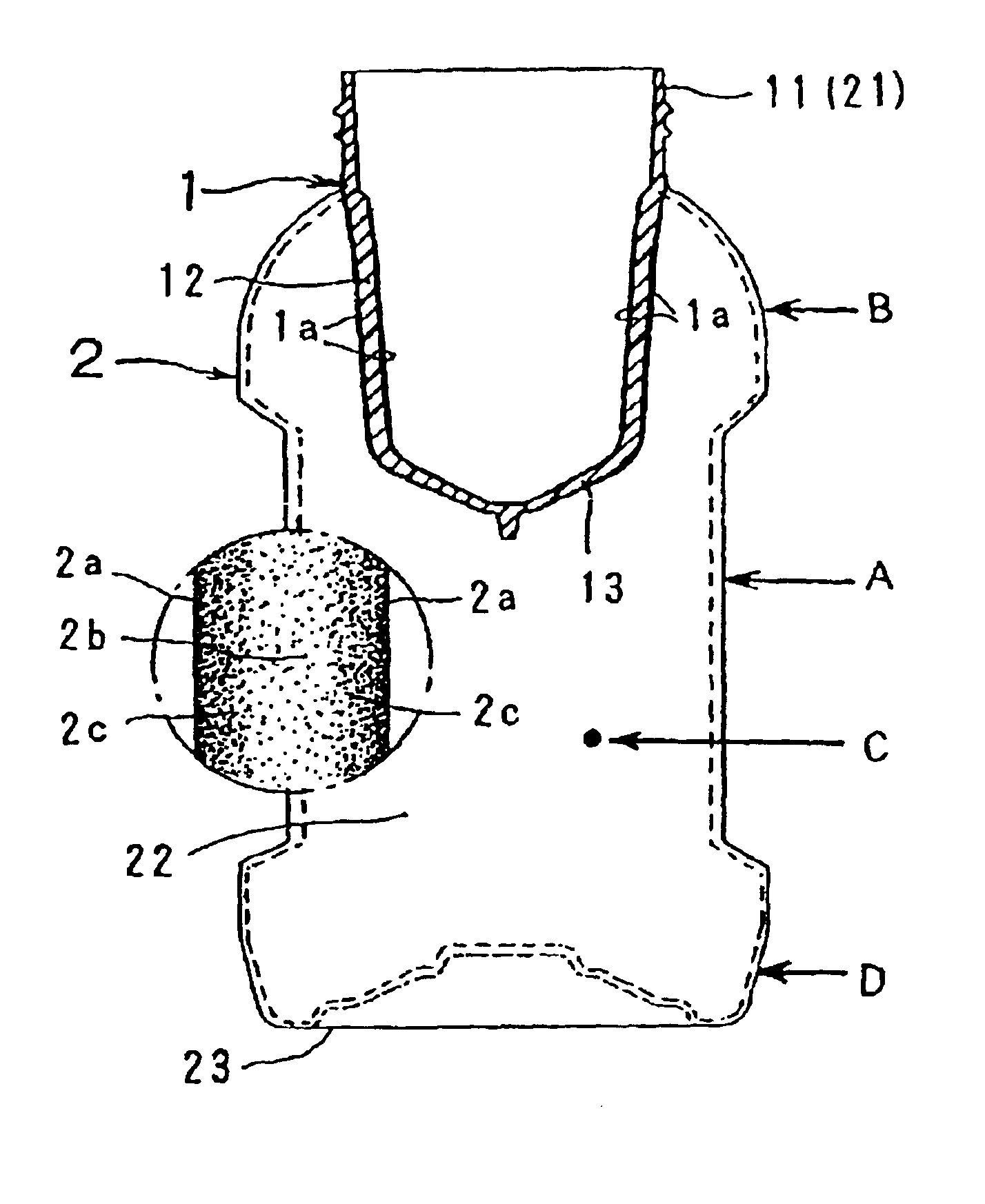
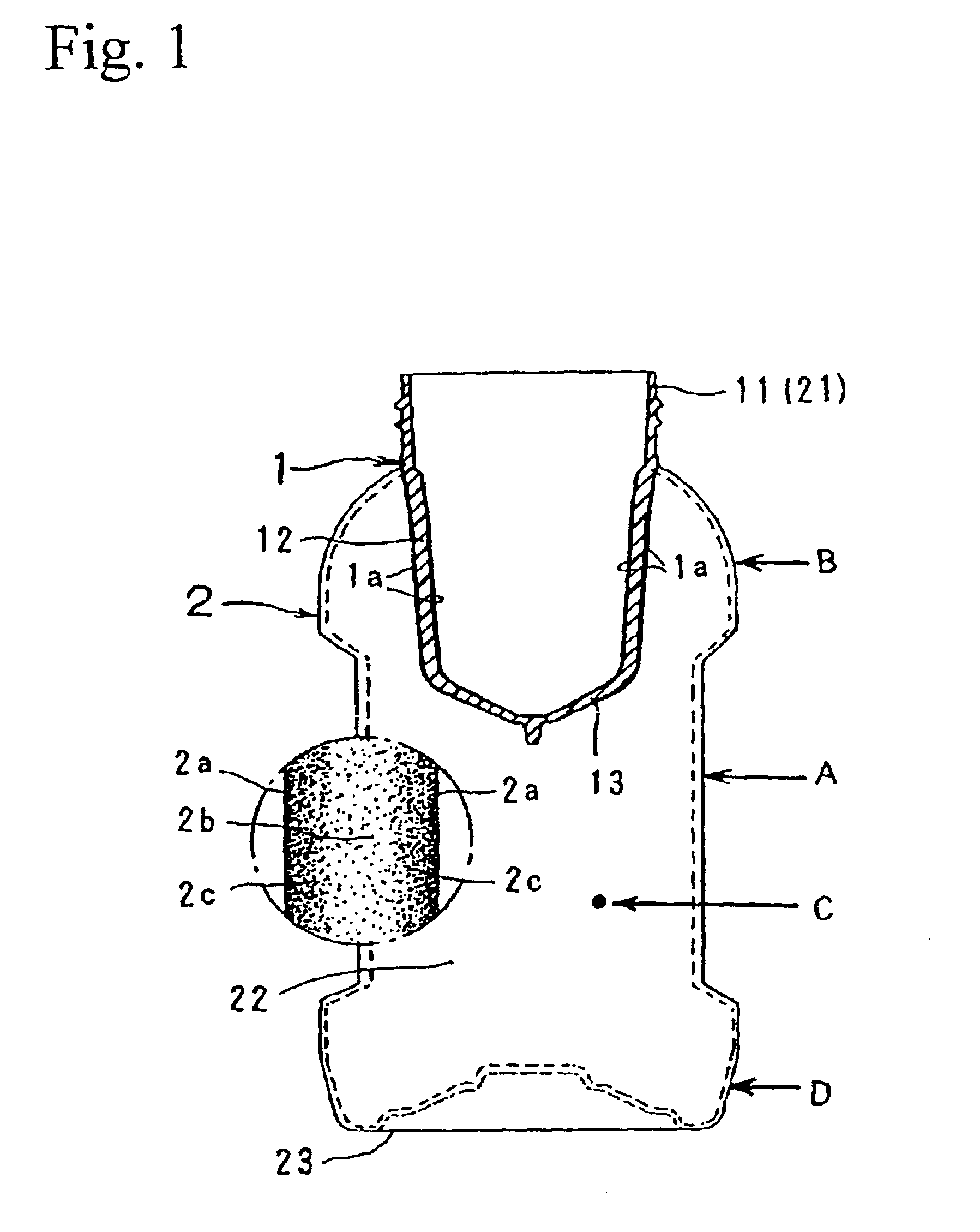
[0014]In the drawing, 1 is a bottomed preform made of a thermoplastic material, for example polyethylene terephthalate, composed of a mouth 11, a body 12 extending to the same and a bottom 13, and molded by injection filling a die with molten plastic material.

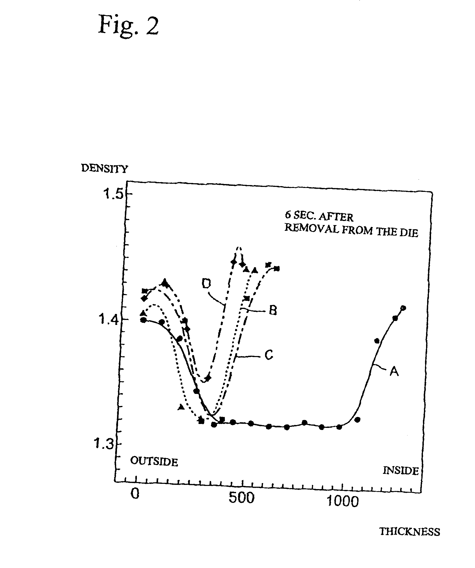
[0015]A wide-mouthed receptacle 2 comprises a mouth 21 by the mouth 11 of the preform 1, a body 22 and a bottom 23 thinly stretch blown from the under side of the mouth, while the wall cross-section is composed of inside and outside surface layers 2a whose crystalline density is high, a core layer 2b presenting a lower density than the surface layers 2a, and an intermediate layer 2c presenting a graduated density between both layers 2a, 2b.

[0016]The wide-mouth receptacle 2 made of multi-layered wall cross-section in respect of the crystalline density can be manufactured by the stretch blow formation according to the hot parison method. However, it is necessary to form the inside and outside surface layers of the preform 1 into...


PUM

PropertyMeasurementUnit
temperatureaaaaaaaaaa
surface temperatureaaaaaaaaaa

Abstract

Improve the strength of the stretch blow receptacle and make the heat resistant treatment easier, by making the receptacle wall cross-section multi-layered in view of crystalline density, and the crystalline density of the surface layer high density. The inventions concerns a thin plastic receptacle 2 molded by stretch blowing of a bottomed preform 1 in the longitudinal and transversal directions. The wall cross-section is composed of inside and outside surface layers 2a whose crystalline density is high by stretching, a core layer 2b presenting a lower density than the surface layers 2a, and an intermediate layer 2c presenting a graduated density between both layers 2a, 2b.

Description

FIELD OF THE INVENTION[0001]The present invention concerns a plastic stretch blow receptacle whose main portions are molded thin, by stretching blowing of an injection molded bottom preform in the longitudinal and transversal directions.BACKGROUND ART[0002]Means for stretch molding of plastic receptacles for packaging such as bottles, wide-mouthed jars or the like include the cold parison method for stretch blowing a preformed bottomed preform into a receptacle by heat softening at a temperature higher than the glass transition point, and the hot parison method for immediately stretch blowing an injection molded soft and bottomed preform into a receptacle, while it maintains a potential heat higher than the glass transition point.[0003]In the cold parison method, it is believed that the preform temperature becomes uniform and the crystalline density of the wall cross-section of the receptacle molded by stretch blowing is also uniformed, because a preform of ambient temperature is he...

Claims


Application Information

Patent Timeline
Patent Type & Authority Patents(United States)
IPC IPC(8): B29C49/22B65D1/02B29C49/08B29C49/06B29K67/00B29L22/00
CPCB29C49/22B65D1/0215B29B2911/14053Y10T428/1352B29B2911/1408B29B2911/14093B29B2911/1412B29B2911/14146B29B2911/14593B29B2911/14633B29B2911/1466B29B2911/14693B29B2911/14713B29C49/06B29C49/08B29L2031/7158Y10T428/1393Y10T428/24479Y10T428/24595Y10T428/2495Y10T428/24992B29B2911/14066B29C2949/3008B29C2949/3012B29C2949/302B29C2949/3016B29C2949/3028B29C2949/3036B29C2949/0817B29C2949/0821B29C2949/0811B29C2949/0826B29C2949/0829B29C2949/0715
Inventor NAKAMURA, YUTAKAMOCHIZUKI, TAKEKAZUYOKOYAMA, ISAMUHINATA, NAOMICHIOOISHI, JIN
Owner A K TECH LAB INC
Why Eureka
Try Eureka