Vehicle headlamp

a headlamp and vehicle technology, applied in the field of vehicle headlamps, can solve the problems of failure to form a light distribution pattern difficulty in forming a light distribution pattern with a desired distribution, etc., and achieve the effect of reducing the occurrence of upward light responsible for glaring, reducing the degree of freedom of shape of a vehicle headlamp, and reducing the occurrence of upward ligh

Inactive Publication Date: 2005-05-10
KOITO MFG CO LTD
View PDF16 Cites 45 Cited by
  • Summary
  • Abstract
  • Description
  • Claims
  • Application Information

AI Technical Summary

Benefits of technology

[0018]As shown by the above-described configurations, a vehicle headlamp of the invention is equipped with a plurality of lamp units employing semiconductor light-emitting elements as light sources, wherein used as the plurality of lamp units are at least two types of lamp units selected from a lamp unit of projector type, a lamp unit of direct projection type, and a lamp unit of reflection type. Hence, the following working-effect can be yielded.
[0019]Specifically, use of lamp units of different radiation modes, such as a lamp unit of projector type, a lamp unit of direct projection type, and a lamp unit of reflection type, enables easy formation of light distribution patterns having different light distribution characteristics.
[0022]The vehicle headlamp of the invention is configured to include a plurality of lamp units, each unit using a semiconductor light-emitting element as a light source. Hence, each lamp unit can be miniaturized. As such, a degree of freedom of shape of a vehicle headlamp can be increased, thereby enabling an attempt to render the vehicle headlamp compact.
[0023]The lamp unit of projector type is designed to project forward an image formed on a focal plane located rearward of the projection lens, and hence a cut-off line having a high contrast ratio can be formed readily. Therefore, when light is radiated in the form of a low-beam light distribution pattern through use of the foregoing configuration, occurrence of upward light responsible for glaring can be minimized, so long as a cut-off line of low-beam light distribution pattern is formed by means of the lamp unit of projector type.

Problems solved by technology

The lamp configuration described in JP-A-2001-266620 enables changing of the shape of a light distribution pattern by division into an illuminating region and a non-illuminating region, but encounters difficulty in forming a light distribution pattern with a desired distribution of luminous intensity.
However, in such a case the following problem will arise.
Therefore, there arises a problem of a failure to form a light distribution pattern of a vehicle headlamp obtained as a merged light distribution pattern in the form of a desired pattern geometry and a desired distribution of luminous intensity.

Method used


Image

  • Vehicle headlamp
  • Vehicle headlamp
  • Vehicle headlamp

Examples


Embodiment Construction

[0037]An embodiment of the invention will be described hereinbelow by reference to the drawings.

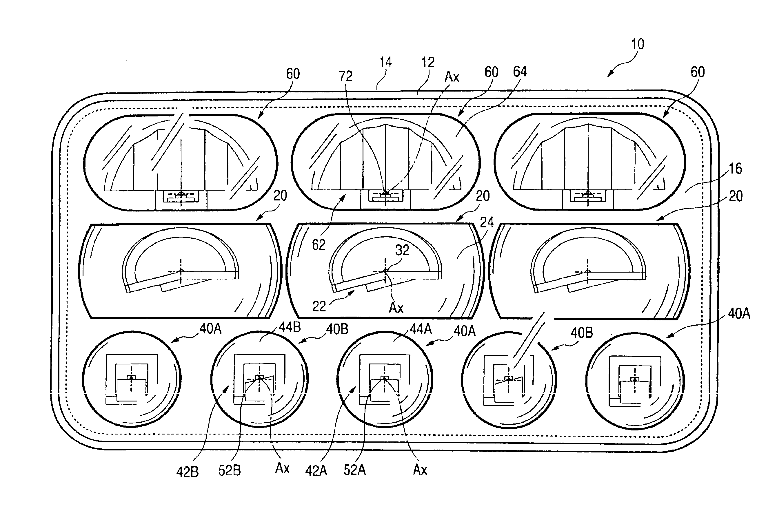
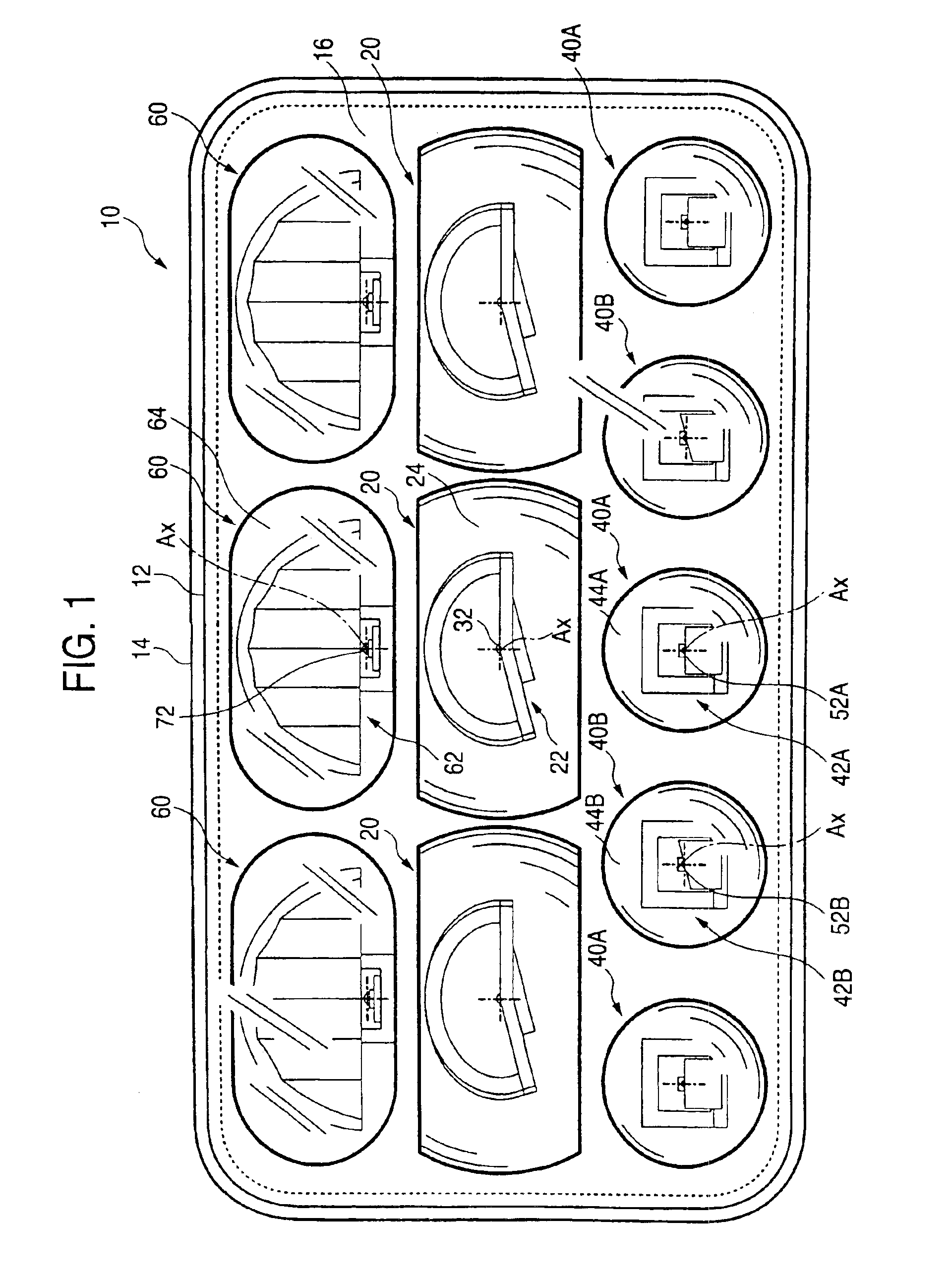
[0038]FIG. 1 is a front view showing a vehicle headlamp 10 according to an embodiment of the invention.

[0039]The vehicle headlamp 10 is a low-beam headlamp. The headlamp is constituted so as to house eleven lamp units 20, 40A, 40B, and 60 in three rows within a lamp chamber, which is formed from a transparent, translucent cover 12 and a lamp body 14.

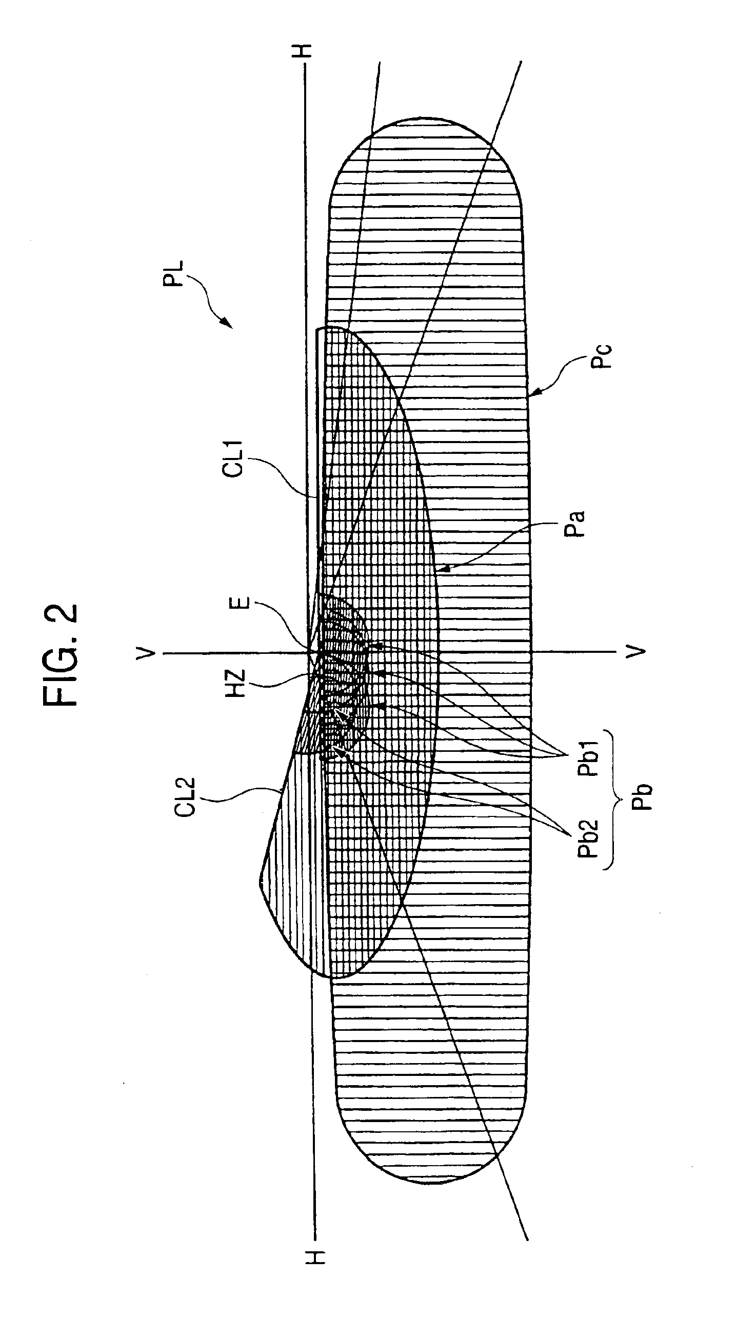
[0040]FIG. 2 is a perspective view for showing a low-beam light distribution pattern PL formed on a virtual vertical screen placed at a position 25 m ahead of a lamp by means of the light output forward from the vehicle headlamp 10.

[0041]The low-beam light distribution pattern PL is a left light distribution pattern having a horizontal cut-off line CL1 and an oblique cut-off line CL2 provided at an upper end of the light distribution pattern. The position of an elbow point E, which is a point of intersection of the cut-off lines CL1 and CL2, i...


PUM


Abstract

A vehicle headlamp is constituted to have a plurality of lamp units having light-emitting diodes as light sources. At that time, three types of lamp units of different radiation modes; that is, a projector-type lamp unit, direct-projection-type lamp units, and a reflection-type lamp unit, are used as the plurality of lamp units. As a result, a low-beam light distribution pattern obtained as a merged light distribution pattern formed from the light rays output from these three types of lamp units can be readily formed in a desired pattern geometry and a desired distribution of luminous intensity.

Description

BACKGROUND OF THE INVENTION[0001]1. Field of the Invention[0002]The invention relates to a vehicle headlamp configured to form a predetermined light distribution pattern. More particularly, the invention relates to a vehicle headlamp using a plurality of lamp units having light-emitting diodes as light sources including a projector-type lamp unit, a direct-projection-type lamp unit, and a reflection-type lamp unit.[0003]2. Description of the Related Art[0004]A light-emitting diode has been used as a light source of a vehicle marker lamp such as a tail lamp. For instance, JP-A-2002-50214 describes a vehicle marker lamp in which a plurality of lamp units, each unit using a light-emitting diode as a light source, are arranged.[0005]JP-A-2001-266620 describes a vehicle headlamp. The headlamp is constructed such that a desired light distribution pattern is formed by selectively illuminating a portion of a plurality of light-emitting diodes arranged in a matrix layout.[0006]The lamp confi...

Claims


Application Information

Patent Timeline
Patent Type & Authority Patents(United States)
IPC IPC(8): B60Q1/04F21V7/00F21S8/10F21S8/12F21V13/00F21W101/10F21Y101/02
CPCB60Q1/04F21S48/1154F21S48/1159F21S48/137F21S48/1163Y10S362/80F21Y2101/02F21Y2115/10F21S41/143F21S41/148F21S41/153F21S41/155F21S41/336F21S41/20F21S41/32F21W2102/00
Inventor TATSUKAWA, MASASHIISHIDA, HIROYUKISAZUKA, KIYOSHI
Owner KOITO MFG CO LTD
Why Eureka
Try Eureka