Adaptive CFL control circuit

a technology of cfl control circuit and compact fluorescent lamp, which is applied in the direction of electrical equipment, instruments, light sources, etc., can solve the problems of non-ignition lamp failure, and achieve the effect of low cost, simplified integrated control circuit and robust electronic ballas

Inactive Publication Date: 2005-05-10
INFINEON TECH AMERICAS CORP
View PDF2 Cites 33 Cited by
  • Summary
  • Abstract
  • Description
  • Claims
  • Application Information

AI Technical Summary

Benefits of technology

[0009]In accordance with the present invention, there is a provided a simple low cost integrated control circuit that provides programmable CFL functional control, in addition to driving a half bridge composed of MOSgated switches to obtain a robust electronic ballast for a CFL. The integrated control circuit according to the present invention is simplified to minimize packaging costs and to fit into a standard integrated circuit package. For example, the integrated control circuit is provided on a chip with eight pins that handle all electronic ballast functions. Four pins are provided to drive a MOSgated half bridge, with two pins set aside for power and a circuit common. The remaining two pins program the electronic ballast minimum frequency and all other functions including preheat operation, lamp ignition and normal operation, as well as a number of fault protection functions. The programmable inputs to the integrated control circuit are coupled to an adaptive control system with a half bridge voltage sensor to accomplish the variety of CFL safety features and functionality.

Problems solved by technology

In addition, the resonant inductor may saturate resulting in a non-ignition lamp failure.

Method used


Image

  • Adaptive CFL control circuit
  • Adaptive CFL control circuit
  • Adaptive CFL control circuit

Examples


Embodiment Construction

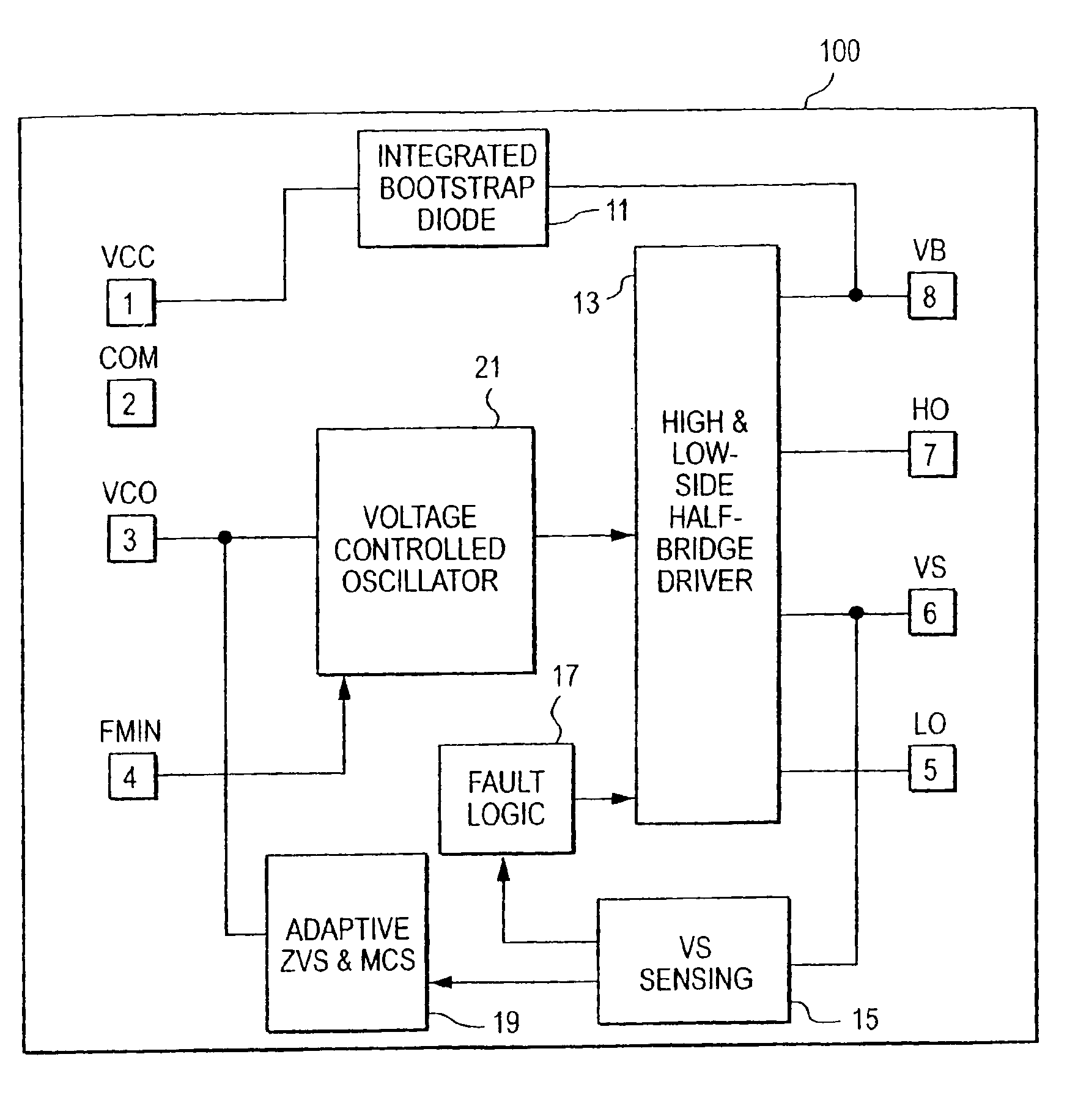
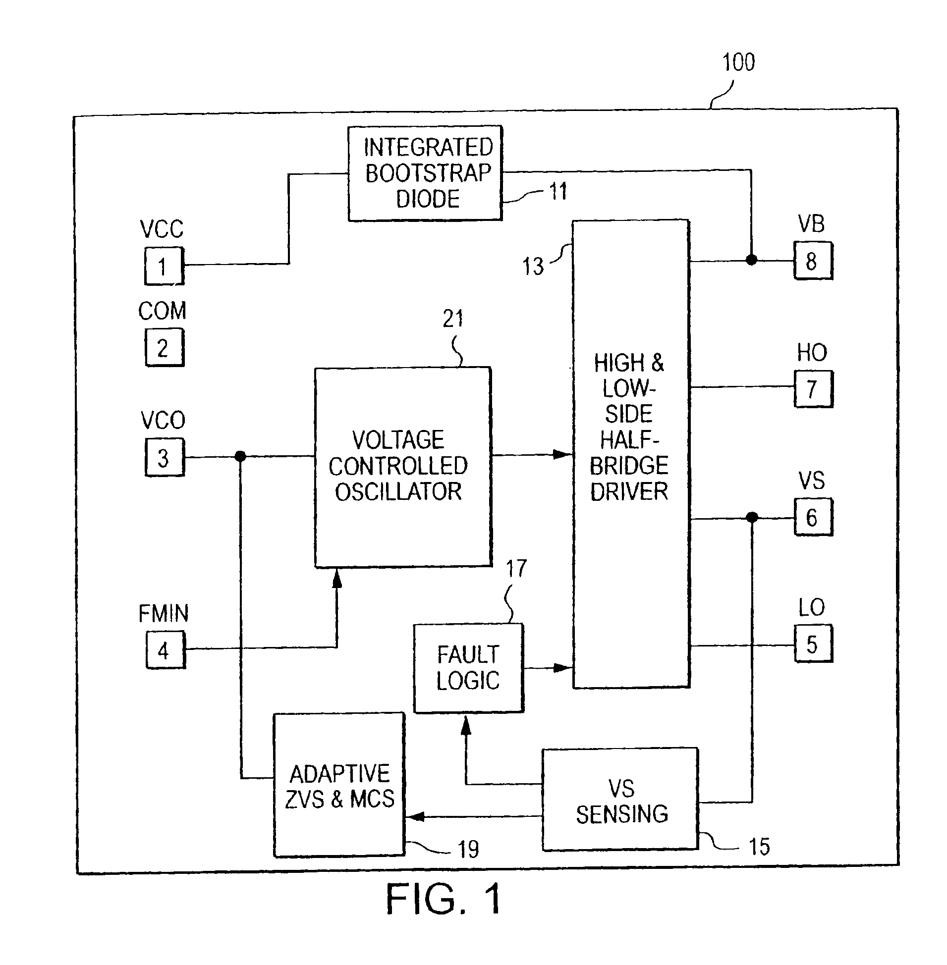
[0026]Referring now to FIG. 1, a block diagram of an integrated control circuit 100 according to the present invention is illustrated. Control circuit 100 includes indications of pinouts for an integrated circuit, or chip, designated by boxes numbered 1-8. Each pin number 1-8 is labeled with a descriptive term indicative of the functionality of the pin. Accordingly, pin 1 and pin 2 are labeled VCC and COM, respectively, to indicate power and ground for integrated control circuit 100. Pins 5-8 are labeled LO, VS, HO, and VB, respectively, which labels refer to typical connections for a half bridge driver. That is, pins 5 and 7 labeled LO and HO are responsible for providing the gate signals to the low and high half bridge power switches, respectively. Pins 6 and 8 labeled VS and VB represent the power supplied to the low and high side switches, respectively. In a typical half bridge configuration, the two half bridge switches are tied together at a node supplied by VS on pin 6, while...


PUM


Abstract

An electronic ballast provides fault detection and safety features for overcurrent protection and hard switching at a half bridge. A voltage controlled oscillator supplies a switching frequency that is modifiable based on operationalfeedback parameters. A feedback circuit senses load current and output voltage to determiner fault conditions and to provide control information for adaptively adjusting the frequency of the voltage controlled oscillator. By appropriately controlling the voltage controlled oscillator output, the electronic ballast maintains a zero volt switching with minimum current switching to achieve an efficient and robust electronic ballast control. The entire control is integrated on a single integrated circuit.

Description

RELATED APPLICATIONS[0001]The present application is based on and claims benefit of U.S. Provisional Application No. 60 / 412,621, filed Sep. 19, 2002, entitled Adaptive CFL Control IC, to which a claim of priority is hereby made. The present application is also related to U.S. application Ser. No. 10 / 616,173 filed on Jul. 8, 2003, entitled Adaptive Ballast Control IC.BACKGROUND OF THE INVENTION[0002]1. Field of the Invention[0003]The present invention relates generally to ballasts for compact fluorescent lamps, and relates more particularly an adaptive ballast control for a compact fluorescent lamp in an integrated circuit.[0004]2. Description of Related Art[0005]Electronic ballasts for fluorescent lighting applications are widely available and include integrated circuits that perform standard functions, application specific integrated circuits that provide additional functionality and micro controllers that permit programmable control of fluorescent lamps. The functions performed by...

Claims


Application Information

Patent Timeline
Patent Type & Authority Patents(United States)
IPC IPC(8): H05B41/282H05B41/298H05B41/28
CPCH05B41/2981H05B41/2828G05F1/575
Inventor RIBARICH, THOMAS J.WILHELM, DANA
Owner INFINEON TECH AMERICAS CORP
Why Eureka
Try Eureka