Vehicular vision system

a vision system and vehicle technology, applied in the field of rearview vision systems, can solve the problems of driver inability to perceive vehicles, objects, other road users, and difficulty in maneuvering in tight spaces, and achieve the effect of enhancing the interpretation of visual information

Inactive Publication Date: 2005-05-10
DONNELLY CORP
View PDF99 Cites 543 Cited by
  • Summary
  • Abstract
  • Description
  • Claims
  • Application Information

AI Technical Summary

Benefits of technology

[0010]The present invention is directed towards enhancing the interpretation of visual information in a rearview vision system by presenting information in a manner which does not require significant concentration of the driver or present distractions to the driver. This is accomplished according to an aspect of the invention in a rearview vision system having at least two image capture devices positioned on the vehicle and directed generally rearwardly with respect to the direction of travel of the vehicle. A display is provided for images captured by the image capture devices. The display dis

Problems solved by technology

However, this is achieved with an increase in image distortion which makes driver awareness of conditions to the side and rear of the vehicle even more difficult.
Furthermore, rearview mirrors protrude a substantial distance from the side of the vehicle, which makes maneuvering in tight spaces more difficult.
The driver cannot perceive vehicles, objects, or other road users in such blind spots without turning his or her body, which interferes with forward-looking visual activities.
Camera-based rearview vision systems for vehicles have not obtained commercial acceptance.
One difficulty with proposed systems has been that they present a large amount of visual information in a manner which is difficult to comprehend.
This difficulty arises from many factors.
This may confuse the driver as to whether more than one object is present.
This results in different vertical positions on the display causing the elongated image to appear disjointed.
This makes the ability to judge distances in a camera system a problem.
Therefore, known camera systems fail to provide to the driver important information where that information is most needed—at small separation distances from surrounding objects.
Another difficulty with camera sys

Method used


Image

  • Vehicular vision system
  • Vehicular vision system
  • Vehicular vision system

Examples


Embodiment Construction

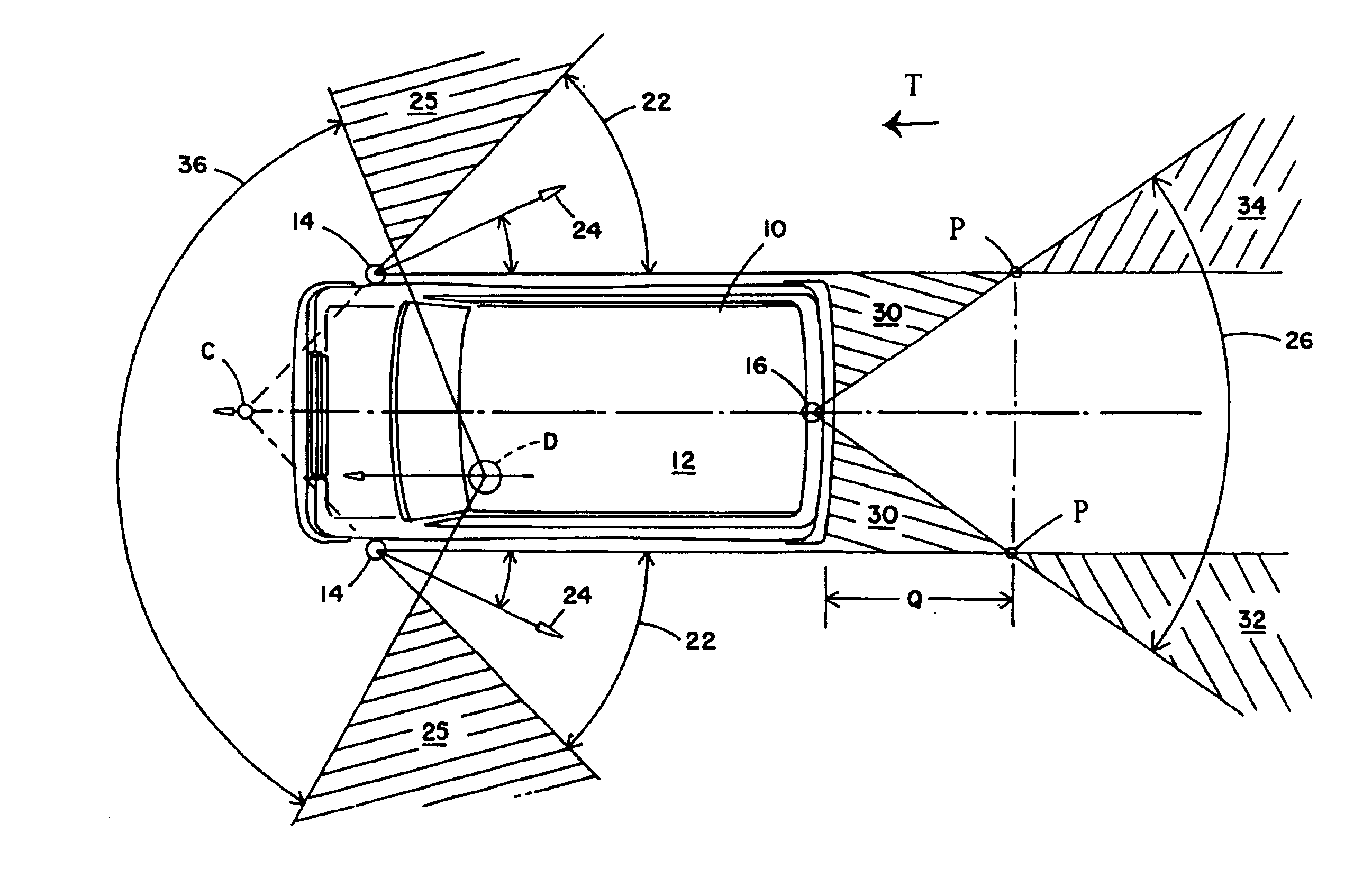
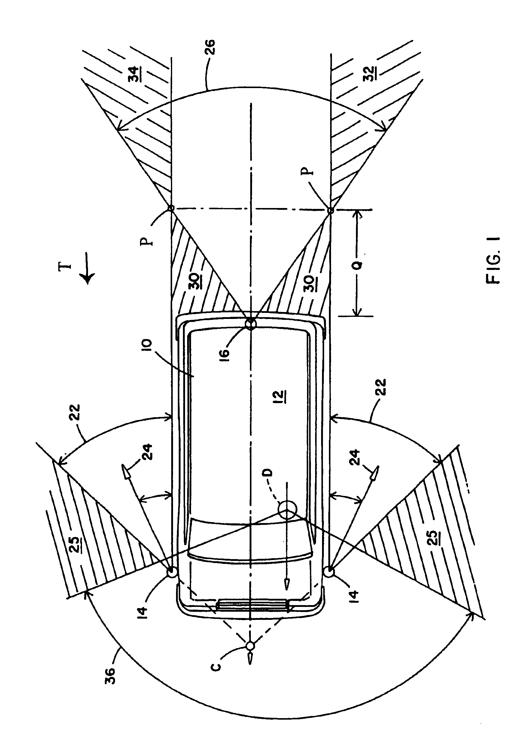
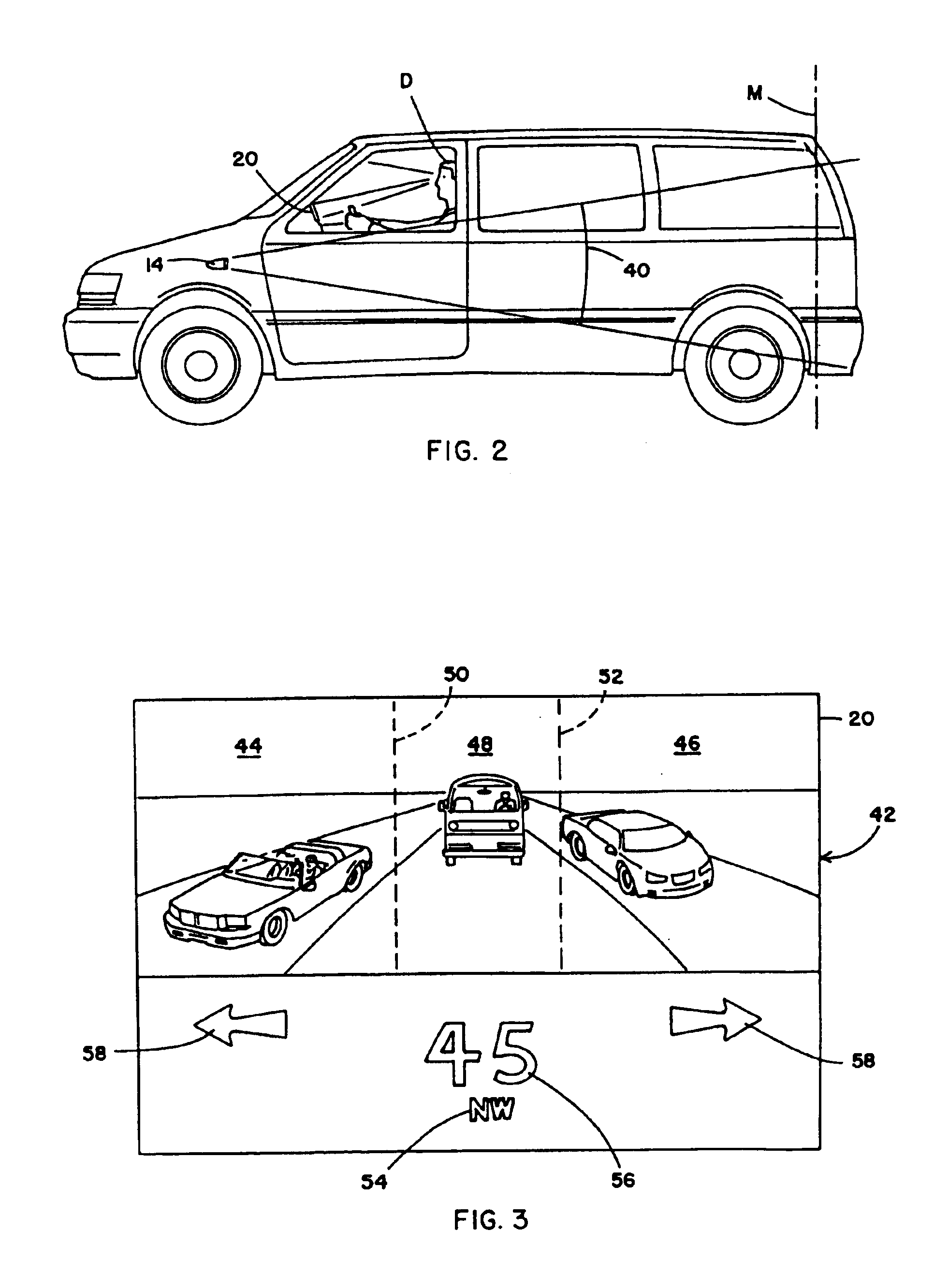
[0044]Referring now specifically to the drawings, and the illustrative embodiments depicted therein, a vehicle 10, which may be an automobile, a light truck, a sport utility vehicle, a van, a bus, a large truck, or the like includes a rearview vision system, generally illustrated at 12, for providing a driver of the vehicle with a view rearwardly of the vehicle with respect to the direction of travel T of the vehicle (FIG. 1). Vision system 12 includes at least two side image capture devices 14 positioned, respectively, on opposite sides of vehicle 10 and a center image capture device 16 positioned on the lateral centerline of the vehicle. All of the image capture devices are directed generally rearwardly of the vehicle. Rearview vision system 12 additionally includes an image processor 18 for receiving data signals from image capture devices 14, 16 and synthesizing, from the data signals, a composite image 42 which is displayed on a display 20.

[0045]As will be set forth in more det...


PUM


Abstract

A vehicle vision system includes a vehicle having first and second spatially separated image capture sensors. The first image capture device has a first field of view having a first field of view portion at least partially overlapping a field of view portion of a second field of view of the second image capture device. A control receives a first image input from the first image capture sensor and a second image input from the second image capture sensor and generates a composite image synthesized from the first image input and the second image input. A display system displays the composite image.

Description

CROSS-REFERENCE TO RELATED APPLICATION[0001]This application is a continuation of patent application Ser. No. 08 / 952,026, filed under 35 U.S.C. §371, filed Nov. 19, 1997, now U.S. Pat. No. 6,498,620, which is based on International Patent Application No. PCT / US96 / 07382, filed May 22, 1996, which claims priority from patent application Ser. No. 08 / 445,527 filed May 22, 1995, now U.S. Pat. No. 5,670,935.BACKGROUND OF THE INVENTION[0002]This invention relates generally to vision systems for vehicles and, more particularly, to rearview vision systems which provide the vehicle operator with scenic information in the direction rearward of the vehicle. More particularly, the invention relates to a rearview vision system utilizing image capture devices, such as CMOS imaging arrays and the like.[0003]A long-felt need in the art of vehicle rearview vision systems is to reduce the amount of time spent gathering information of the condition around the vehicle in order to safely carry out a vehi...

Claims


Application Information

Patent Timeline
IPC IPC(8): B60R1/00H04N7/18
CPCB60R1/00H04N7/18H04N7/181B60R2300/105B60R2300/106B60R2300/107B60R2300/205B60R2300/207B60R2300/303B60R2300/305B60R2300/802B60R2300/804B60R2300/8053B60R2300/806B60R2300/8066B60R2300/8086B60R2300/103
Inventor SCHOFIELD, KENNETHLARSON, MARK L.VADAS, KEITH J.
Owner DONNELLY CORP
Why Eureka
Try Eureka