
Video signal conversion processing apparatus and method

a technology of video signal and conversion apparatus, applied in the direction of signal generator with optical-mechanical scanning, picture reproducer using projection device, television system, etc., can solve the problem that standard interlace signal cannot be output, and achieve the effect of high degree of accuracy

Inactive Publication Date: 2005-05-10
SONY CORP
View PDF28 Cites 18 Cited by
  • Summary
  • Abstract
  • Description
  • Claims
  • Application Information

AI Technical Summary

Benefits of technology

[0015]It is an object of the present invention to provide a signal processing apparatus and method by which an interlace signal can be up or down converted with a high degree of accuracy.
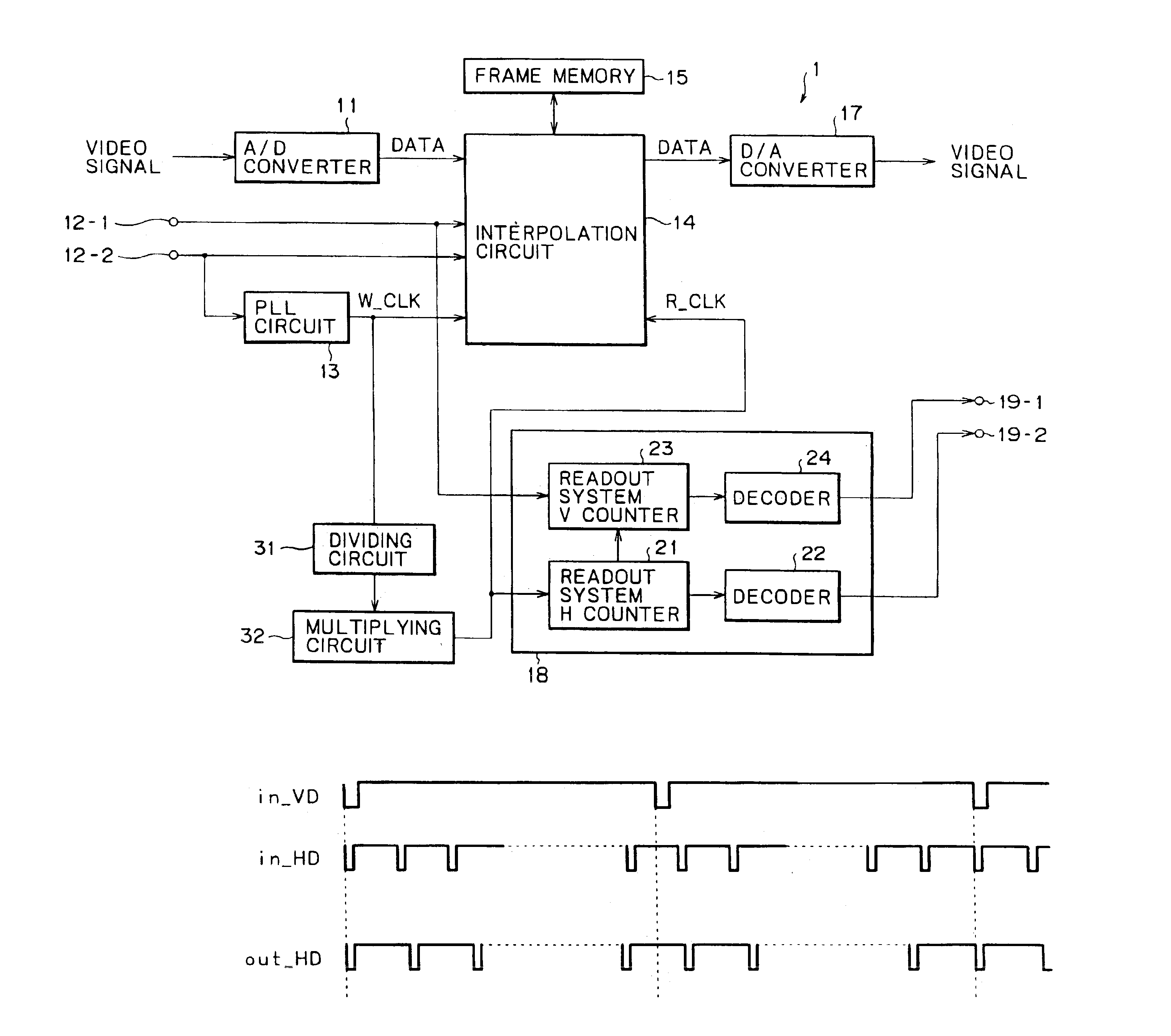
[0020]In the signal processing apparatus and the signal processing method, a first signal is produced based on a horizontal synchronizing signal included in an input video signal, and the input video signal is stored in synchronism with the thus produced first signal. Further, the frequency of the first signal is first divided by a first value and then multiplied by a second value to produce a second signal. Then, the stored video signal is read out in synchronism with the thus produced second signal, and the pixel number or the scanning line number of the thus read out video signal is converted. Therefore, an interlace signal can be up or down converted with a high degree of accuracy.
[0025]In the signal processing apparatus and the signal processing method, a reference signal is generated, and the frequency of the generated reference signal is first divided by a first value and then multiplied by a second value to produce a predetermined signal. Then, an input video signal is stored in synchronism with the thus produced predetermined signal. Thereafter, the stored video data is read out in synchronism with the generated reference signal, and the pixel number or the scanning line number of the read out video data is converted. Therefore, an interlace signal can be up or down converted with a high degree of accuracy with a minimized circuit scale.

Problems solved by technology

Consequently, there is a problem that a standard interlace signal cannot be output.

Method used


Image

  • Video signal conversion processing apparatus and method
  • Video signal conversion processing apparatus and method
  • Video signal conversion processing apparatus and method

Examples


Embodiment Construction

[0041]Referring to FIG. 8, there is shown an example of configuration of an up-down converter to which the present invention is applied. The up-down converter shown is generally denoted at 1 and has a pair of input terminals 12-1 and 12-2 and a pair of output terminals 19-1 and 19-2. The up-down converter 1 includes an A / D converter 11, a PLL circuit 13, an interpolation circuit 14, a frame memory 15, a D / A converter 17, and an output synchronizing signal generation circuit 18 which includes a readout system H counter 21, a decoder 22, a readout system V counter 23 and a decoder 24, all similar to those of the conventional up-down converter 1 described hereinabove with reference to FIG. 1. Therefore, like parts or elements are denoted by the same reference numerals and overlapping description is omitted herein to avoid redundancy. The up-down converter 1 according to the present configuration additionally includes a dividing circuit 31 and a multiplying circuit 32.

[0042]The dividing...


PUM


Abstract

A signal processing apparatus and method for up or down conversion of an interlace signal with a high degree of accuracy. The frequency of a write system clock supplied from a PLL circuit is divided by N by a dividing circuit and then multiplied by M by a multiplying circuit to produce a readout system clock. An interpolation circuit writes a video signal into a frame memory in synchronism with the write system clock from the PLL circuit, and reads out the video signal in synchronism with the readout system clock from the multiplying circuit.

Description

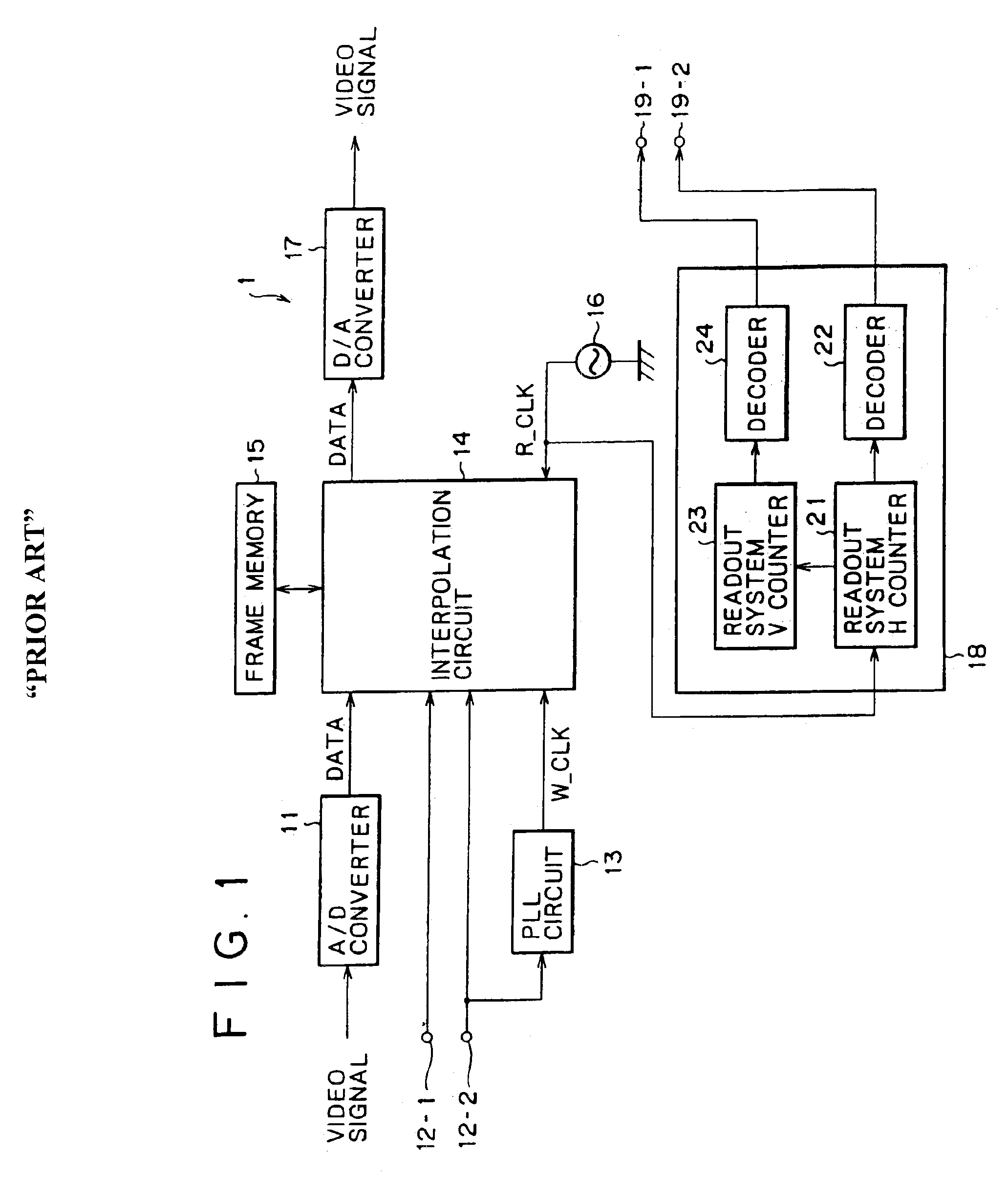
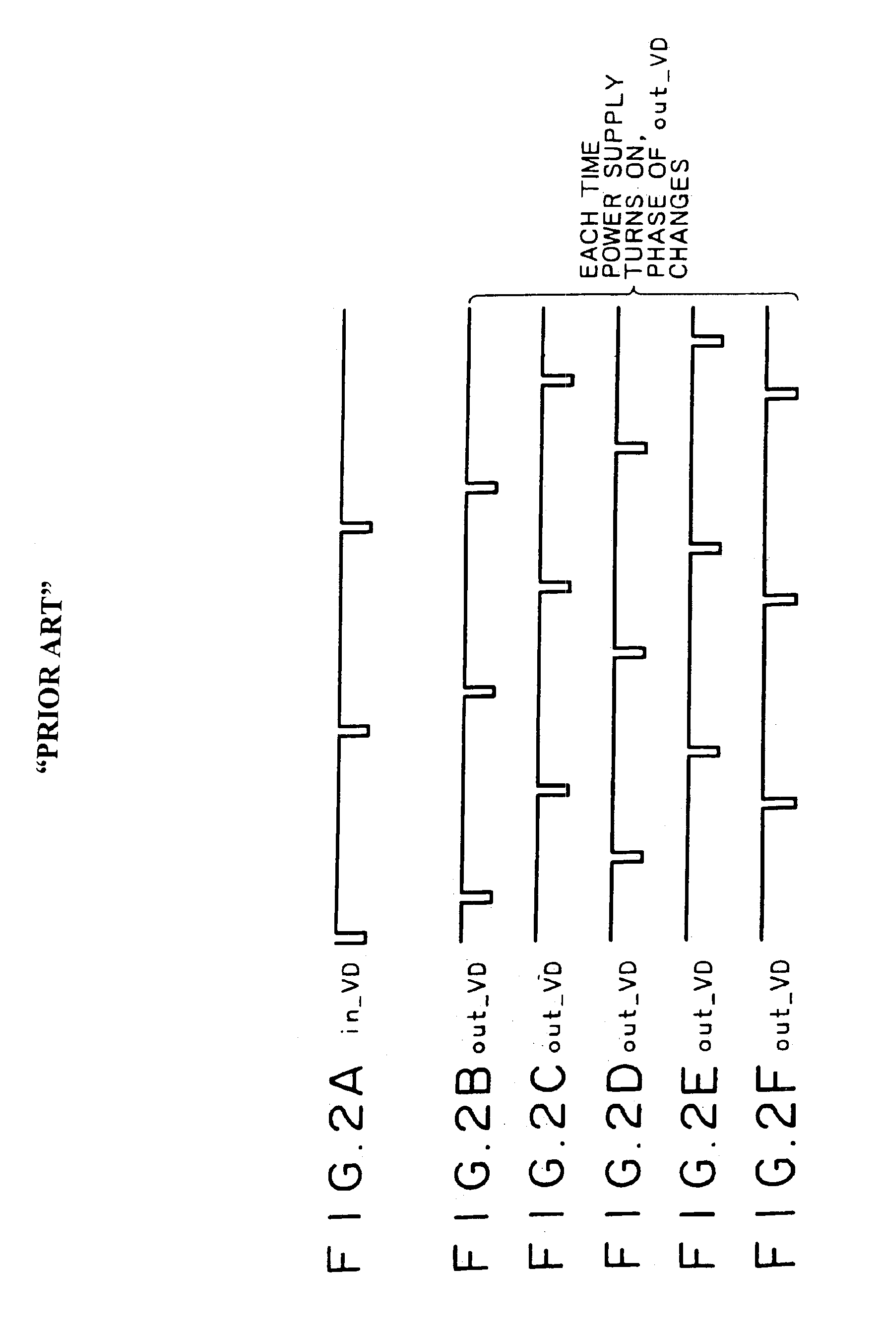
CROSS-REFERENCE TO RELATED APPLICATIONS[0001]The present application claims the benefit of Japanese Application No. P2000-135617 filed May 9, 2000, the disclosure of which is hereby incorporated by reference herein.BACKGROUND OF THE INVENTION[0002]The present invention relates to a signal processing apparatus and method, and more particularly to a signal processing apparatus and method wherein a video signal of the HDTV (High Definition Television) system is down converted into another video signal of the NTSC system.[0003]A conventionally known up-down converter typically has such a configuration as shown in FIG. 1. Referring to FIG. 1, the up-down converter generally denoted at 1 includes an A / D (Analog to Digital) converter 11 which A / D converts a video signal input thereto from an external apparatus not shown and supplies a resulting digital video signal to an interpolation circuit 14. The external apparatus further inputs a vertical synchronizing signal (in_VD) (hereinafter ref...

Claims


Application Information

Patent Timeline
Patent Type & Authority Patents(United States)
IPC IPC(8): H04N7/01
CPCH04N7/0105H04N7/0135H04N7/0125H04N7/01
Inventor UEKI, NOBUO
Owner SONY CORP
Learn More