Eureka AIR delivers breakthrough ideas for toughest innovation challenges, trusted by R&D personnel around the world.

Mold frame structure of liquid crystal display

Active Publication Date: 2005-05-10
LG DISPLAY CO LTD
View PDF7 Cites 32 Cited by
  • Summary
  • Abstract
  • Description
  • Claims
  • Application Information

AI Technical Summary

Benefits of technology

[0031]An advantage of the present invention is to provide a mold frame structure of an LCD in which a main frame accommodating a display panel is made in a slim and lightweight structure and ground terminal of PCBs attached to the rear side of the main frame are stably grounded to keep up with the slimness and the lightness of the LCD.
[0032]Additional features and of the invention will be set forth in part in the description which follows, and in part will be apparent from the description, or may be learned by practice of the invention. The objectives and other advantages of the invention will be realized and attained by the structure particularly pointed out in the written description and claims hereof as well as the appended drawings.
[0033]To achieve these and other advantages and in accordance with the purpose of the invention, as embodied and broadly described herein, there is provided, an LCD mold frame assembly including a main frame, a plurality of connection plate coupling parts corresponding to PCBs attached to the rear side of the main frame, wherein the connection plate coupling parts are integral to the main frame along edges of the main frame, and a plurality of ground connection plates coupled to the plurality of connection plate coupling parts, for grounding ground terminals of the PCBs to the upper case.
[0034]In another aspect of the present invention an LCD display includes a display panel, a mold frame assembly comprising a main frame, a plurality of connection plate coupling parts corresponding to PCBs attached to the rear side of the main frame, wherein the connection plate coupling parts are integral to the main frame along edges of the main frame, and a plurality of ground connection plates coupled to the plurality of connection plate coupling parts, for grounding ground terminals of the PCBs to the upper case, a backlight unit stacked with the display panel in the main frame, a panel guide frame coupled with the main frame, and a top case coupled with the main frame.

Problems solved by technology

However, CRTs have many disadvantages regarding miniaturization or portability.
However, according to the mold frame of the LCD constructed as described above, the cover plate acting as a ground plate is attached to provide a separate ground of the PCB on the rear side of the main frame, resulting in increased thickness and weight.
Further, the additional process of attaching the cover plate for grounding the ground terminals of the PCBs increases the manufacturing cost and degrades the production efficiency.

Method used


Image

  • Mold frame structure of liquid crystal display
  • Mold frame structure of liquid crystal display
  • Mold frame structure of liquid crystal display

Examples


Embodiment Construction

[0047]Reference will now be made in detail to an embodiment of the present invention, example of which is illustrated in the accompanying drawings.

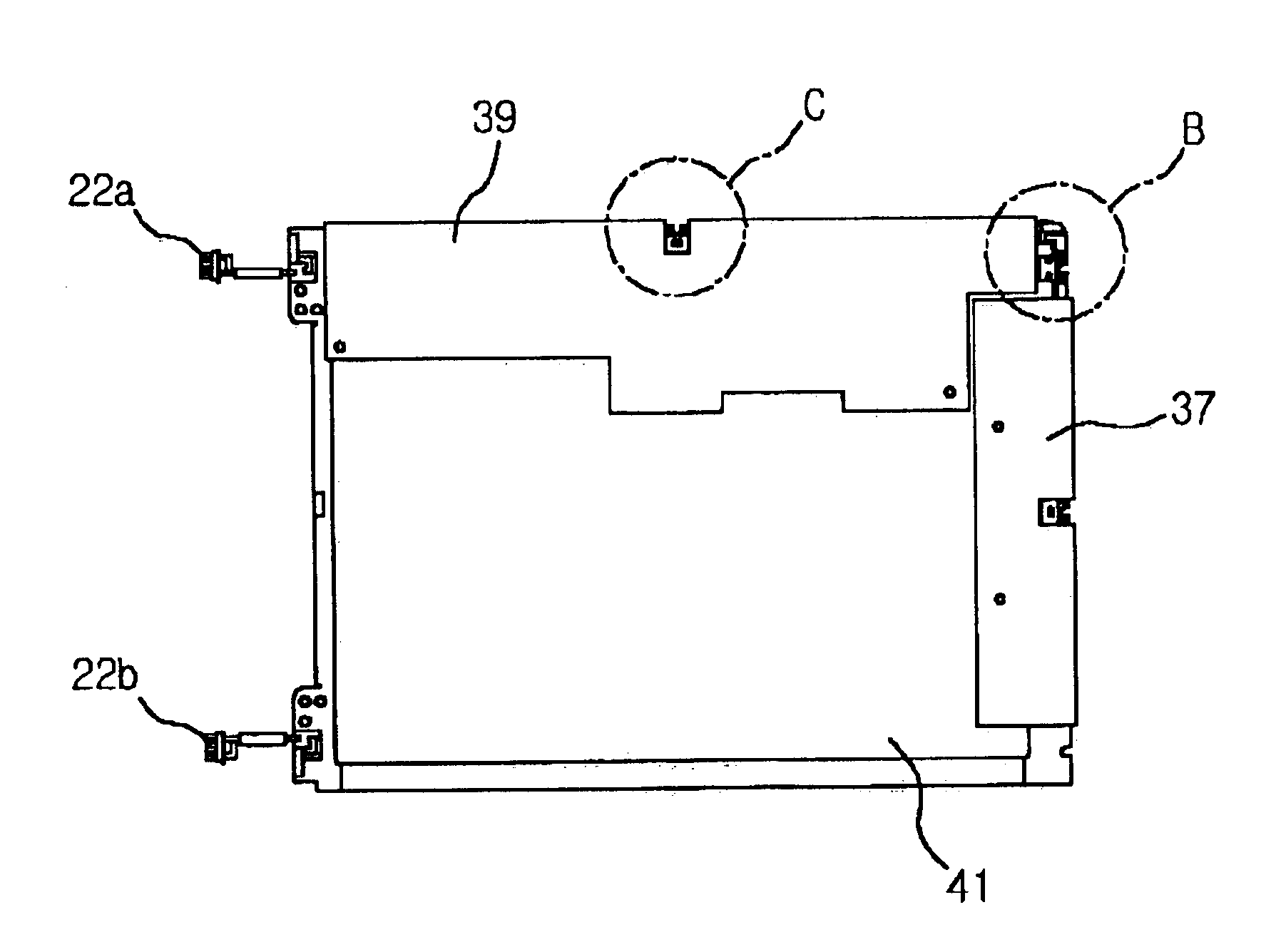
[0048]FIG. 4 is a plan view of a mold frame of a liquid crystal display according to the present invention. A liquid crystal display panel, and a backlight unit including a plurality of optical sheets are accommodated in a stack structure in a main frame 41. The main frame 41 is coupled with a panel guide (not shown) such that the LCD panel is not moved. A top case (not shown) of metal is also coupled with the main frame 41 so as to protect the elements accommodated in the main frame 41 from an external impact.

[0049]Connectors 22a and 22b for supplying power to the backlight extend from both edges of the main frame 41. Although not shown in the drawings, a gate PCB 37 or a data PCB 39 is folded on the rear side of the main frame 41. A plastic transparent shield cover is attached on the PCBs 37 and 39.

[0050]In particular, in case of the pr...


PUM


Abstract

Disclosed is a mold frame structure of an LCD including a main frame, a plurality of connection plate coupling parts corresponding to PCBs attached to the rear side of the main frame, wherein the connection plate coupling parts are integral to the main frame along edges of the main frame, and a plurality of ground connection plates coupled to the plurality of connection plate coupling parts, for grounding ground terminals of the PCBs to the upper case.

Description

[0001]This application claims the benefit of Korean Patent Application No. 2002-52988, filed on Sep. 3, 2002, which is hereby incorporated by reference for all purposes as if fully set forth herein.BACKGROUND OF THE INVENTION[0002]1. Field of the Invention[0003]The present invention relates to a liquid crystal display (LCD), and more particularly, to a mold frame structure of an LCD in which a main frame accommodating an LCD panel and an optical sheet is slim and lightweight and a ground terminal of a PCB attached to the rear side of the main frame is stably grounded.[0004]2. Description of the Related Art[0005]Recently, as technology in the semiconductor industries rapidly develops, slim and lightweight liquid crystal displays (LCDs) having improved performance are produced. Up to now, cathode ray tubes (CRTs) widely used as information display devices have many advantages in view of performance or price. However, CRTs have many disadvantages regarding miniaturization or portabilit...

Claims


Application Information

Patent Timeline
IPC IPC(8): G02F1/13G02F1/1333
CPCG02F1/13452G02F1/1333
Inventor HWANG, YUN HO
Owner LG DISPLAY CO LTD
Why Eureka
Eureka Blog
Learn More