Double confocal scanning microscope

a scanning microscope and confocal technology, applied in the field of double confocal scanning microscopes, can solve the problem of reducing the contribution of secondary maxima

Inactive Publication Date: 2005-05-10
LEICA MICROSYSTEMS CMS GMBH
View PDF9 Cites 14 Cited by
  • Summary
  • Abstract
  • Description
  • Claims
  • Application Information

AI Technical Summary

Benefits of technology

[0007]It is therefore an object of the present invention to elim

Problems solved by technology

A modification of the detection characteristics or of the illumination and detection character

Method used


Image

  • Double confocal scanning microscope
  • Double confocal scanning microscope
  • Double confocal scanning microscope

Examples


Embodiment Construction

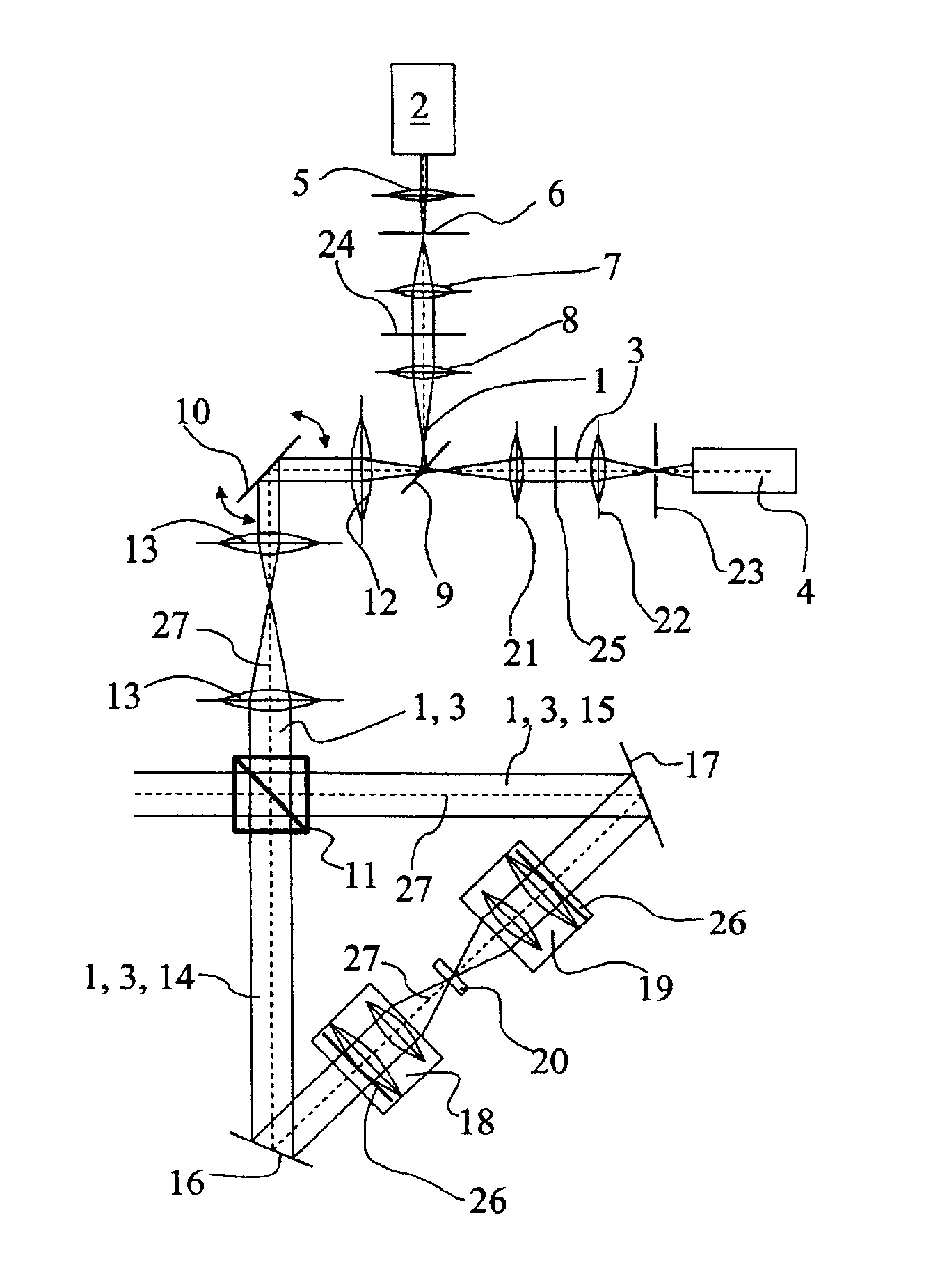
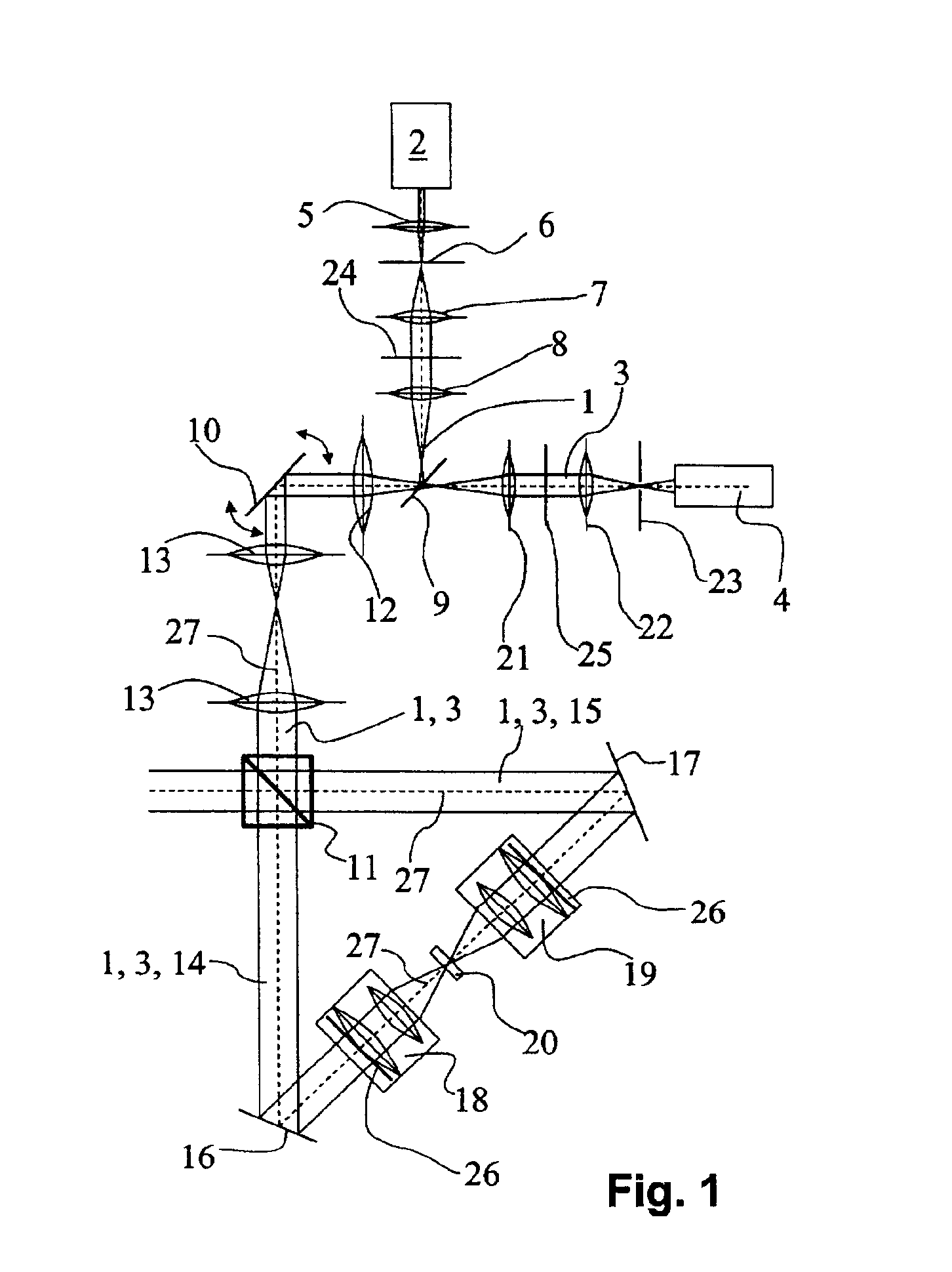
[0023]FIG. 1 shows a double confocal scanning microscope having an illuminating beam path 1 of a light source 2 and a detection beam path 3 of a detector 4.

[0024]Light of light source 2 is focused by means of lens 5 onto illumination pinhole 6. A first intermediate image of illumination pinhole 6 is formed by way of lenses 7, 8. The light of illuminating beam path 1 is then reflected by dichroic beam splitter 9 toward beam deflection device 10. A lens 12 that collimates the beam is provided between dichroic beam splitter 9 and beam deflection device 10. Beam deflection device 10 comprises a mirror that reflects the illuminating light. The mirror of beam deflection device 10 is mounted pivotably about two axes, so that the illuminating light can be deflected or scanned by appropriate pivoting of the mirror. Two lenses 13, 13 are arranged between beam deflection device 10 and beam splitter 11. Beam splitter 11 divides illuminating beam path 1 into two beam path segments 14, 15. The li...


PUM


Abstract

The present invention concerns a double confocal scanning microscope having an illuminating beam path (1) of a light source (2) and a detection beam path (3) of a detector (4), and in order to eliminate at their cause the problems of reconstruction methods. To do so, at least one optical component (24, 25) acting on the illuminating and/or detection beam path (1, 3) is provided, and is configured in such a way that it influences the amplitude and/or phase and/or polarization of the light; and the characteristics of the double confocal illumination and/or detection are thereby modifiable.

Description

CROSS REFERENCE TO RELATED APPLICATIONS[0001]Referenced-applications[0002]This application claims priority of the German patent application 101 07 095.0, filed on Feb. 14, 2001, which is incorporated by reference herein.BACKGROUND OF INVENTION[0003]The present invention concerns a double confocal scanning microscope having an illuminating beam path of a light source and a detection beam path of a detector.[0004]EP 0 491 289 A1 discloses a double confocal scanning microscope in which the light of a light source is divided into two partial beams, and each partial beam is focused with the aid of a respective microscope objective onto a common specimen point. The two microscope objectives are arranged on different sides of the specimen plane that is common to them. At the specimen point, this interferometric illumination causes formation of an interference pattern that, in the case of constructive interference, exhibits a principal maximum and several secondary maxima. The illumination ...

Claims


Application Information

Patent Timeline
IPC IPC(8): G02B21/00G02B21/14
CPCG02B21/0032G02B21/0076G02B21/0068G02B21/0056
Inventor GUGEL, HILMARBEWERSDORF, JOERGHELL, STEFAN W.
Owner LEICA MICROSYSTEMS CMS GMBH
Why Eureka
Try Eureka