Subsurface borehole evaluation and downhole tool position determination methods

Inactive Publication Date: 2005-05-10
SCHLUMBERGER TECH CORP
View PDF22 Cites 25 Cited by
  • Summary
  • Abstract
  • Description
  • Claims
  • Application Information

AI Technical Summary

Problems solved by technology

Further, the threshold filtering method of the prior art can mask background noise, but it does not take into account the effect of different acoustic matching between the PEEK material and the borehole fluid.

Method used


Image

  • Subsurface borehole evaluation and downhole tool position determination methods
  • Subsurface borehole evaluation and downhole tool position determination methods
  • Subsurface borehole evaluation and downhole tool position determination methods

Examples


Embodiment Construction

[0034]The method according to the invention enables measuring the shape of a borehole.

[0035]It also enables determining the tool's preferential position in the borehole, allowing for better interpretation of other well logging data.

[0036]FIG. 5 shows a drill string 501 with a well logging tool 502, such as an ultrasonic tool, disposed in a borehole 503 through an earth formation 504. The tool 502 can be any conventional logging instrument used to make acoustic measurement, as shown, for example in U.S. Pat. Nos. 5,354,956, 5,852,587, and 5,387,767. Alternatively, the tool 502 can also be any known instrument of the lowered into the borehole 503 via a wireline or coiled tubing for borehole evaluation (not shown). The tool 502 houses a transducer 505 of the type shown, for example, in U.S. Pat. No. 5,354,956 (assigned to the present assignee). The transducer 505 window 506 is exposed to the mud 507 within the borehole 503.

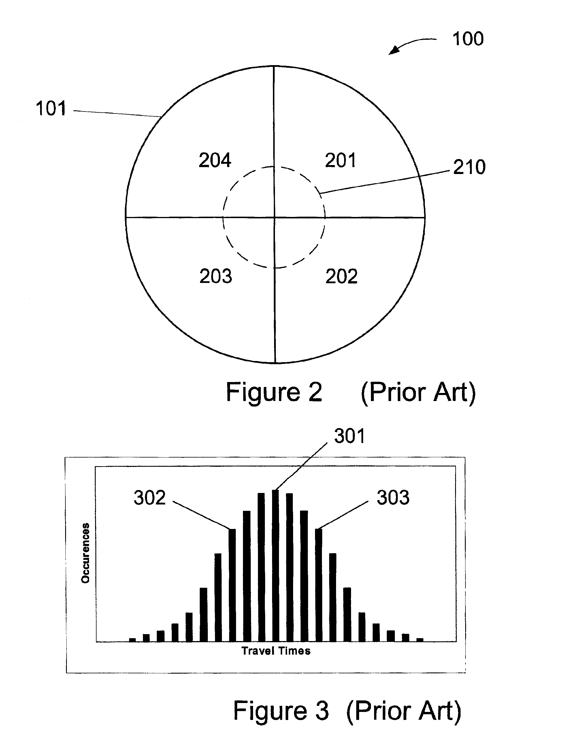
[0037]FIG. 6 shows the azimuthal plane 100 of the borehole 101 ...


PUM


Abstract

Methods for processing ultrasonic signal data to evaluate subsurface properties and tool orientation. Acoustic signals are transmitted into a plurality of azimuthal borehole positions. Formation echo signal transit time distributions are then determined in a plurality of azimuthal sectors for the acoustic signals. Front face echo signal transit times are also measured and farther-mode and closer-mode transit times are determined for the distribution of formation echo signals. Farther and closer tool standoffs are determined for the azimuthal sectors and a borehole diameter is determined from a summation including standoffs in opposing sectors. The standoffs are also used to determine a preferential tool position.

Description

BACKGROUND OF THE INVENTION[0001]1. Field of the Invention[0002]The invention relates generally to the field of well logging. More specifically, the invention relates to techniques for processing ultrasonic signal data to evaluate subsurface properties and tool orientation.[0003]2. Background Art[0004]Ultrasonic tools or instruments or calipers are one of several types of measurement tools used, including while drilling, to measure the size of a borehole. An ultrasonic tool induces a transducer that emits an acoustic signal and then detects the echo signals that are reflected from the borehole wall. The time that it takes the acoustic signal to return to the tool is proportional to the distance that the signal traveled.[0005]A “front face echo” results from reflection of part of the acoustic signal from an interface between an acoustic transducer or sensor external window (called the “front face” of the sensor) and a fluid in the borehole. The borehole fluid or “mud” is pumped throu...

Claims


Application Information

Patent Timeline
Patent Type & Authority Patents(United States)
IPC IPC(8): E21B47/08E21B47/00G01V1/44G01V1/40
CPCG01V1/44E21B47/082E21B47/085
Inventor PABON, MIGUEL F.SLOAN, W. ROBERT
Owner SCHLUMBERGER TECH CORP
Why Eureka
Try Eureka