Fiber optic light mixer

a fiber optic and light mixer technology, applied in the direction of optical radiation measurement, instruments, spectrometry/spectrophotometry/monochromators, etc., can solve the problems of inability to accurately measure, drawbacks, and different light attenuation of light from one or more of these fibers, so as to improve the structure of the light mixer and achieve high degree of light mixing , the effect of improving the mixer structur

Inactive Publication Date: 2005-05-10
HUTCHINSON TECH
View PDF18 Cites 63 Cited by
  • Summary
  • Abstract
  • Description
  • Claims
  • Application Information

AI Technical Summary

Benefits of technology

[0009]The present invention is an improved light mixer structure for combining light from a plurality of individual optical fibers into a single optical transmission device. One embodiment of the light mixer structure includes a plurality of optical send fibers having input

Problems solved by technology

A drawback of the use of individual send fibers is that light from one or more of these fibers may be attenuated differently than the light from other fibers due to inhomogeneities on the surface of the tissue where the light exits the

Method used


Image

  • Fiber optic light mixer
  • Fiber optic light mixer
  • Fiber optic light mixer

Examples


first embodiment

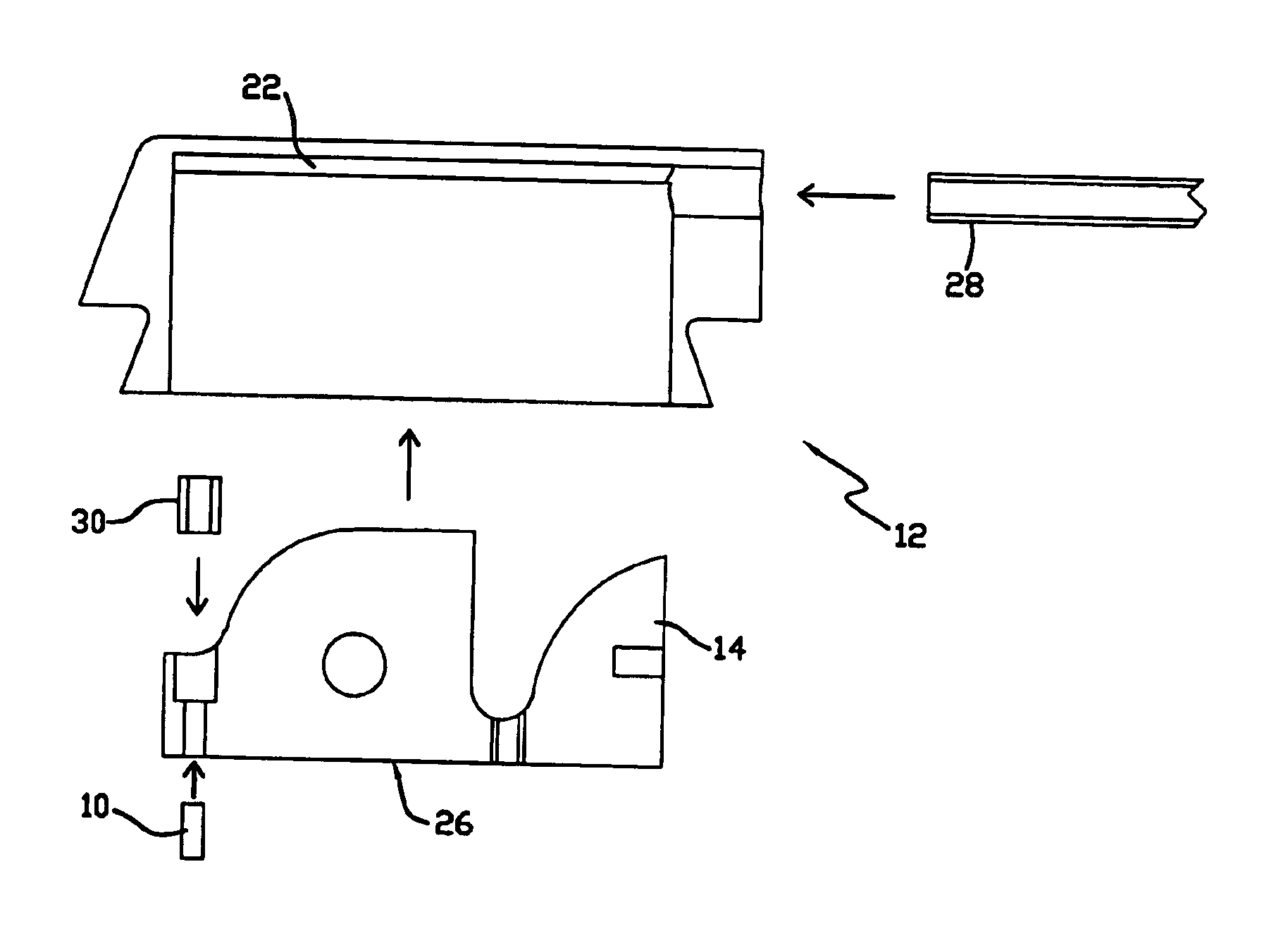
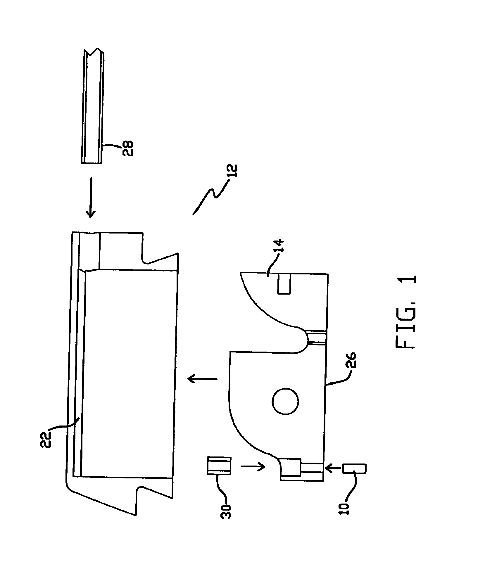
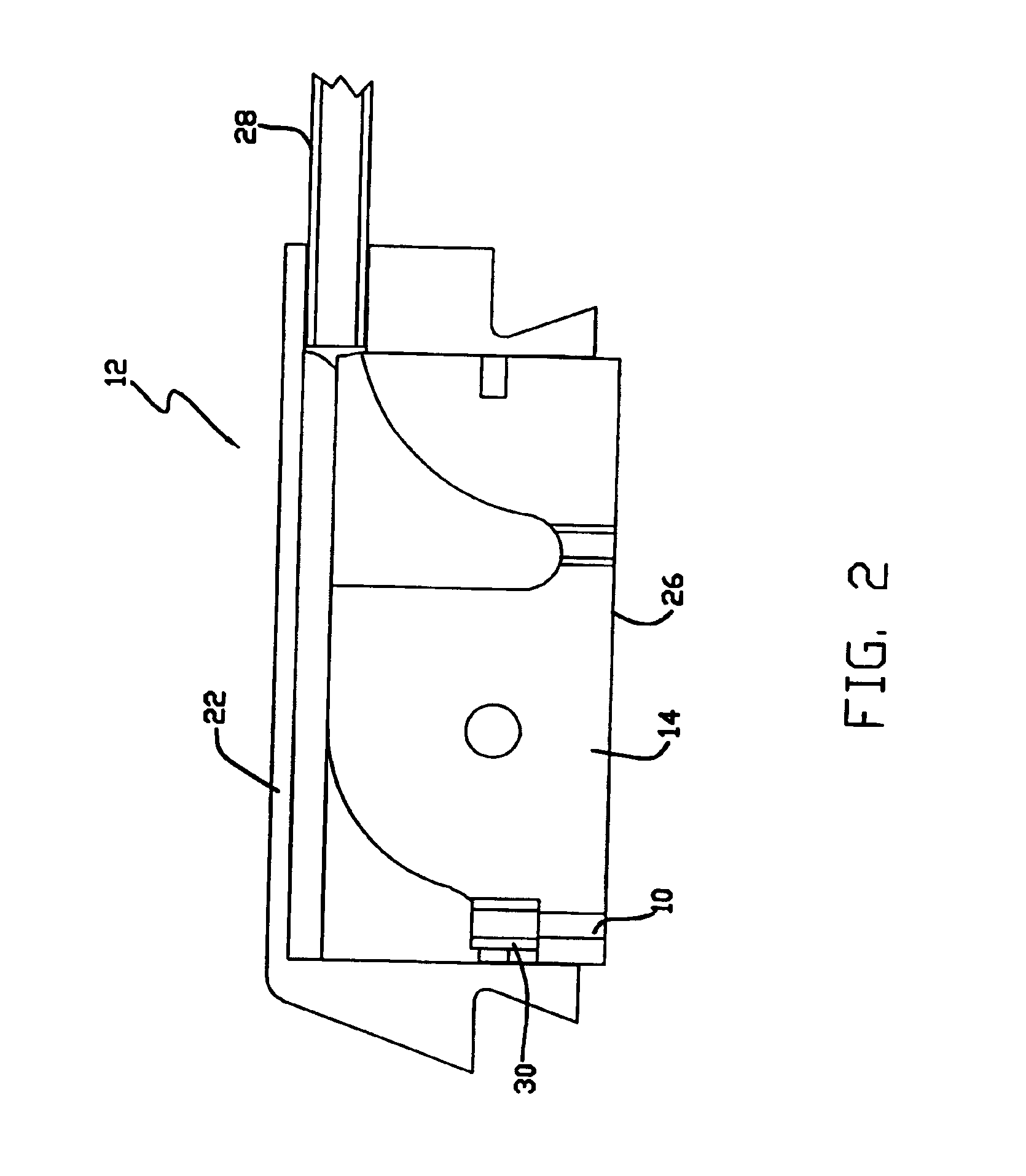
[0022]FIGS. 1-6 illustrate an optical probe 12 which can be used in connection with the instrument shown in the Anderson et al. U.S. Pat. No. 5,879,294 and which includes a light mixer 10 in accordance with the present invention. Briefly, and as shown, the probe 12 includes an insert 14 for holding a number of optical fibers 16, 18 and 20, a housing 22 into which the insert is mounted and a disposable elastomeric tip 24 which is releasably mounted to the housing. The optical fibers 16, 18 and 20, which terminate at a tissue-facing surface 26 of the tip insert 14, are coupled between the housing 22 and instrument (not shown) within a cable housing 28. The illustrated embodiment of the probe 12 has 4 send fibers 16 through which light of different wavelengths from the instrument (provided by narrow bandwidth LEDs) is transmitted to the probe. The ends of the send fibers 16 are sealed in a ferrule 30. The light mixer 10 is a section of optical fiber located between the fiber ferrule 30...

second embodiment

[0027]A probe assembly 100 which includes a light mixer assembly 110 and probe tip 112 in accordance with the present invention can be described with reference to FIGS. 9-12. The assembly 100 includes a cable housing 128 through which a plurality of send fibers 116 extend between the light mixer assembly 110 and light sources (not shown). In one embodiment the length of the send fibers 116 within the cable housing 128 is about 270 cm. A second cable housing 150 houses a mixer fiber 152 which extends between the assembly 110 and the tissue facing surface 126 of the probe insert 114. Mixer fiber 152 is about 30.5 cm long in one embodiment of the invention. The light mixer assembly 110 effectively splices the send fibers 116 to the mixer fiber 152 and includes a connector formed by outer shell 160, inner shell 162, send fiber ferrule 164, mixer fiber ferrule 166 and alignment pin 168. The send fibers 16 extend through the connector outer shell 160 and into send fiber ferrule 164. The e...


PUM


Abstract

An optical structure for combining light from a plurality of individual optical fibers into a single optical transmission device. The structure can be incorporated into the optical probe of a spectrophotometric instrument and includes a plurality of optical send fibers having input and output ends and an optical light mixer having input and output ends. The output ends of the send fibers are secured in optical communication with the input end of the light mixer.

Description

REFERENCE TO RELATED APPLICATIONS[0001]1. This application claims the benefit of U.S. application Ser. No. 09 / 585,144, filed on Jun. 1, 2000 and entitled “Fiber Optic Light Mixer”, which claims the benefit of U.S. Provisional Application Ser. No. 60 / 137,390 filed on Jun. 3, 1999 and entitled “Fiber Optic Light Mixer.”[0002]2. Reference is hereby made to the following commonly assigned and copending U.S. patent applications which are incorporated herein by reference:[0003]i). Ser. No. 09 / 584,990 filed on Jun. 1, 2000 and entitled “Calibration Mode Recognition And Calibration Algorithm For Spectrophotometric Instrument.”[0004]ii). Ser. No. 09 / 584,862 filed on Jun. 1, 2000 and entitled “Disposable Tissue Probe Tip.”FIELD OF THE INVENTION[0005]The present invention is a light mixer for use in connection with an optical probe of a spectrophotometric-type instrument. In particular, the invention is a mixer for combining the different wavelength light beams from a plurality of discrete opt...

Claims


Application Information

Patent Timeline
IPC IPC(8): A61B5/00G01J3/00G01J3/10G02B6/38G02B6/28G01J3/02
CPCA61B5/14552G01J3/02G01J3/0218G02B6/3885G01J3/10A61B2562/146G02B6/2808G02B6/3845G02B6/3873
Inventor LEWANDOWSKI, MARK S.QUAST, KENNETH R.MYERS, DEAN E.SCHMIDT, MARK A.
Owner HUTCHINSON TECH
Why Eureka
Try Eureka