Subscriber station with duplex antenna amplifier

a duplex antenna and amplifier technology, applied in the field of radio engineering, can solve the problems of high cost of coaxial communication cables that provide low loss at high frequencies, loss in radio communications lines connecting antennas and transceiving equipment, and 20 db, so as to improve system power consumption. economic

Inactive Publication Date: 2005-05-10
ALEXANDR VASILIEVICH GARMONOV +1
View PDF7 Cites 16 Cited by
  • Summary
  • Abstract
  • Description
  • Claims
  • Application Information

AI Technical Summary

Benefits of technology

[0013]The goal of the present invention is to improve system power consumption economy, transmitter / receiver signal attenuation in cable being fully compensated.

Problems solved by technology

In higher frequency ranges radio equipment designers encounter the problem of losses in the radio communications line connecting antenna and transceiving equipment.
Coaxial communication cables that provide low losses at high frequencies are very expensive.
Even these, if of considerable length, cause 20 dB and higher losses.
However, insufficient compensation of losses between the communication device and antenna imposes constrains on the application possibility for such a device.
However, the use of such a device is limited by the frequency range because in the UHF range switching frequency should be above signal spectrum carrier frequency.
This enhancer, however, is not economic because there is no mode control is available to it.
However, this device does not compensate for losses in case of long wavelength of coaxial cable.

Method used


Image

  • Subscriber station with duplex antenna amplifier
  • Subscriber station with duplex antenna amplifier
  • Subscriber station with duplex antenna amplifier

Examples


Embodiment Construction

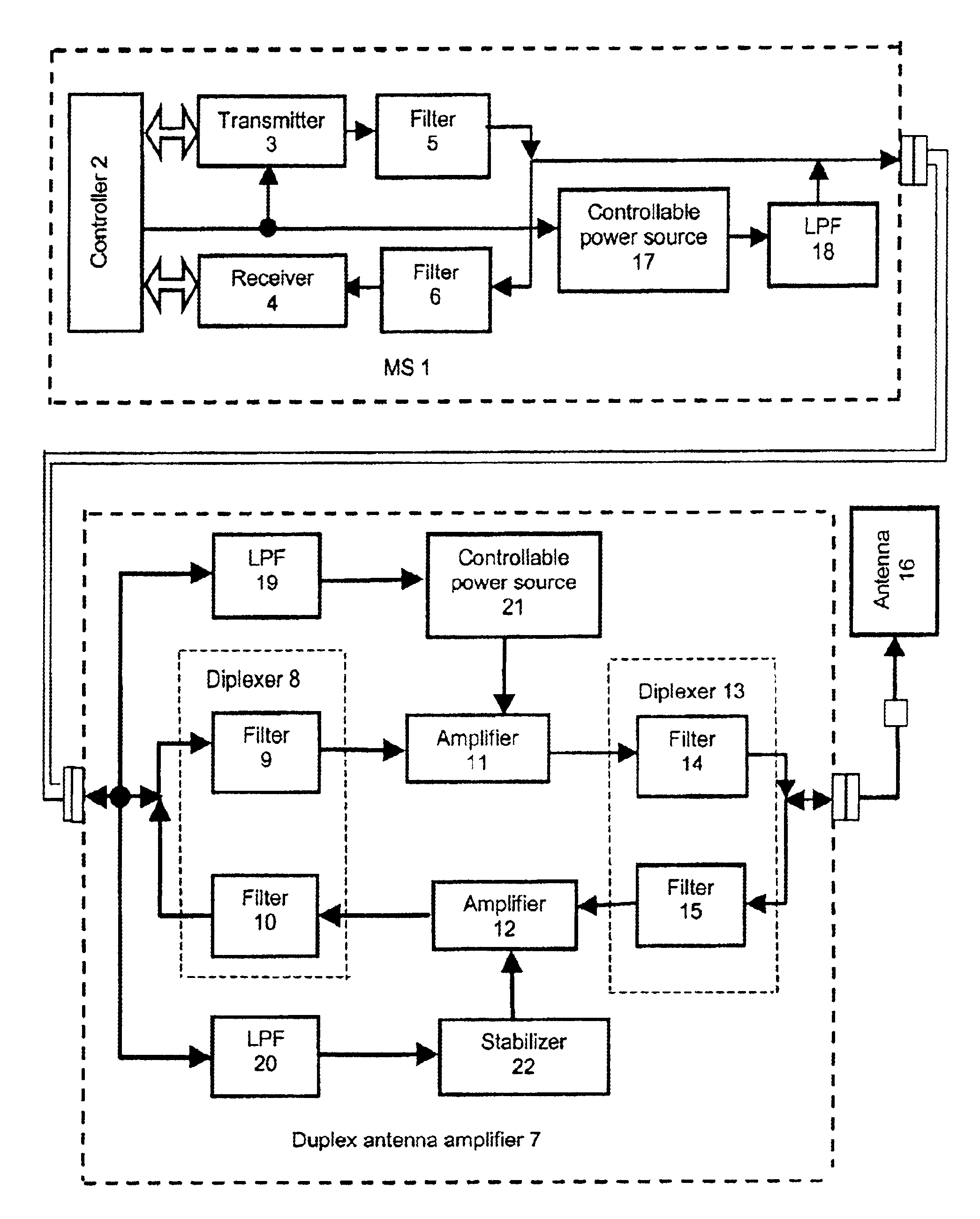
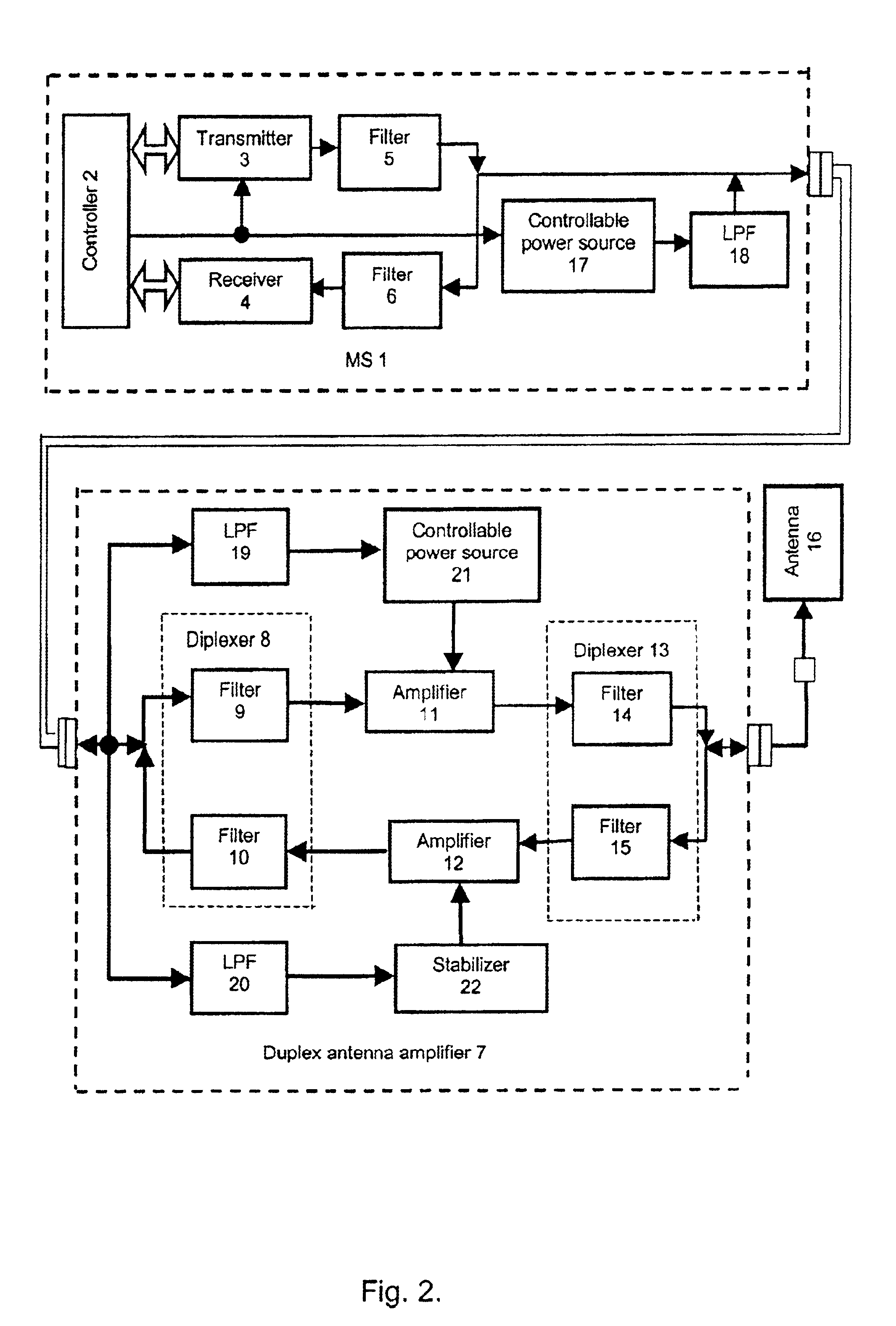
[0031]The block diagram of the proposed device of the first variant is shown in FIG. 2.

[0032]The subscriber set is composed of MS 1 and duplex antenna amplifier 7 both linked by a communication line, and antenna 16 linked to duplex antenna amplifier 7.

[0033]According to the present invention, MS 1 comprises controller 2, the inputs / outputs of which are connected to the outputs / inputs of transmitter 3 and receiver 4. The output of transmitter 3 via first filter 5 is connected to the output / input of MS 1. The input of receiver 4 via second filter 6 is linked to the input / output of MS 1. The control output of controller 2 is joined with the control input of transmitter 3. Additionally, controllable power supply 17, the input of which is connected to the control output of controller 2, is introduced into MS 1. The output of controllable power supply 17 via first LPF 18 is connected to the output / input of MS 1.

[0034]Duplex antenna amplifier 7, according to the present invention, comprise...


PUM


Abstract

For the purpose of making the system more economic, given full compensation of transmitter and receiver signal attenuation in the communication cable, the circuit controlling transmitter enable/disable status, including a controllable power source (control command converter) and a low pass filter separating a receive/transmit UHF signal from a lower frequency up to direct voltage) signal, a number of control commands, is introduced into mobile station, mobile station having autonomous power supply.
According to the first variant of the device, the control command, having passed the low pass filter (19), enables the power source (21) control from which power is supplied to the power amplifier (11) whose amplification is selected so as to compensate attenuation of the transmitter signal traveling from mobile station (1) to antenna (16). The voltage supplied from the mobile station (1) via the communication cable is applied to a stabilizer (22) via the other low pass filter (20) isolating the supply circuit from radio frequency receive and transmit signals.
According to the second variant of the device, a splitter (23) and rejector (24) are used in the duplex antenna amplifier (7). This makes implementation of antenna amplifier simpler and cheaper.

Description

FIELD OF TECHNOLOGY[0001]The present invention relates to radio engineering, particularly, to the devices for amplification of signals transmitted via radio communication lines in both directions at a common frequency band and can be applied to radio communications systems, for example, cellular communications systems.DESCRIPTION OF THE RELATED ART[0002]In higher frequency ranges radio equipment designers encounter the problem of losses in the radio communications line connecting antenna and transceiving equipment. Coaxial communication cables that provide low losses at high frequencies are very expensive. Even these, if of considerable length, cause 20 dB and higher losses. Consequently, the resulting performance is not infrequently degraded. In practice, antenna amplifiers are used to control the power supplied to antenna and compensate the attenuation of radio signals in communication cables.[0003]An antenna circuit for multi-band antenna is described in U.S. Pat. No. 5,258,728 “...

Claims


Application Information

Patent Timeline
Patent Type & Authority Patents(United States)
IPC IPC(8): H04B3/36H04B1/52H04B1/38H04B1/50H04B3/06H04L5/14
CPCH04B1/3877H04B3/06H04B1/52
Inventor GARMONOV, ALEXANDR VASILIEVICHDODIK, SERGEI NIKOLAEVICHZHEREBJATIEV, ANATOLY MAXIMOVICHGRISHCHUK, YAROSLAV VLADIMIROVICH
Owner ALEXANDR VASILIEVICH GARMONOV
Why Eureka
Try Eureka