System for controlling the operation of modules using information transmitted from a control device via a data bus, a trigger device and a test circuit

a module and data bus technology, applied in the field of system for controlling the operation of modules, can solve the problem of not being able to distinguish between firing instructions for different firing devices, and achieve the effect of large flexibility and reliability

Inactive Publication Date: 2005-05-10
SIEMENS AG
View PDF15 Cites 55 Cited by
  • Summary
  • Abstract
  • Description
  • Claims
  • Application Information

AI Technical Summary

Benefits of technology

[0005]The invention discloses developing a system in such a way that a large degree of flexibility and reliability in terms of the actuation capability of the individual modules is provided.

Problems solved by technology

However, in the known system, it is not possible to distinguish between firing instructions for different firing devices, for example firing devices for side airbags and firing devices for front airbags.

Method used


Image

  • System for controlling the operation of modules using information transmitted from a control device via a data bus, a trigger device and a test circuit
  • System for controlling the operation of modules using information transmitted from a control device via a data bus, a trigger device and a test circuit
  • System for controlling the operation of modules using information transmitted from a control device via a data bus, a trigger device and a test circuit

Examples


Embodiment Construction

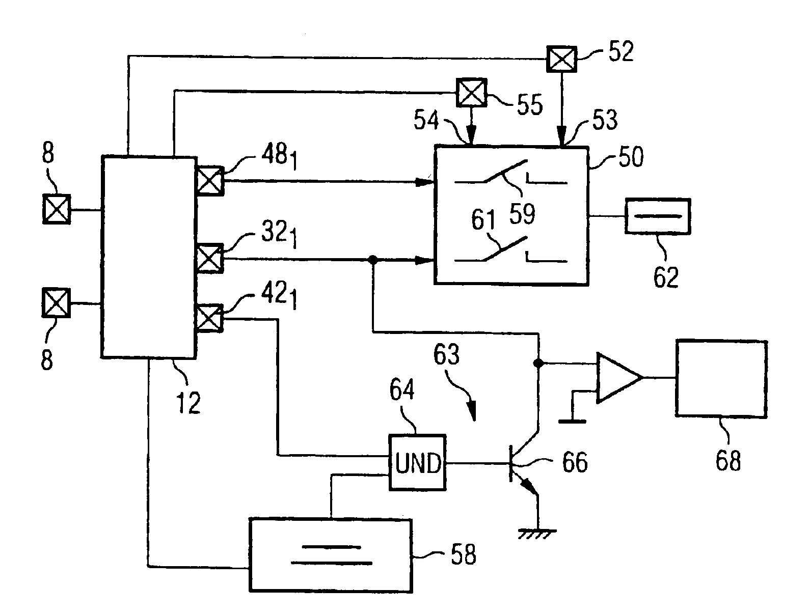
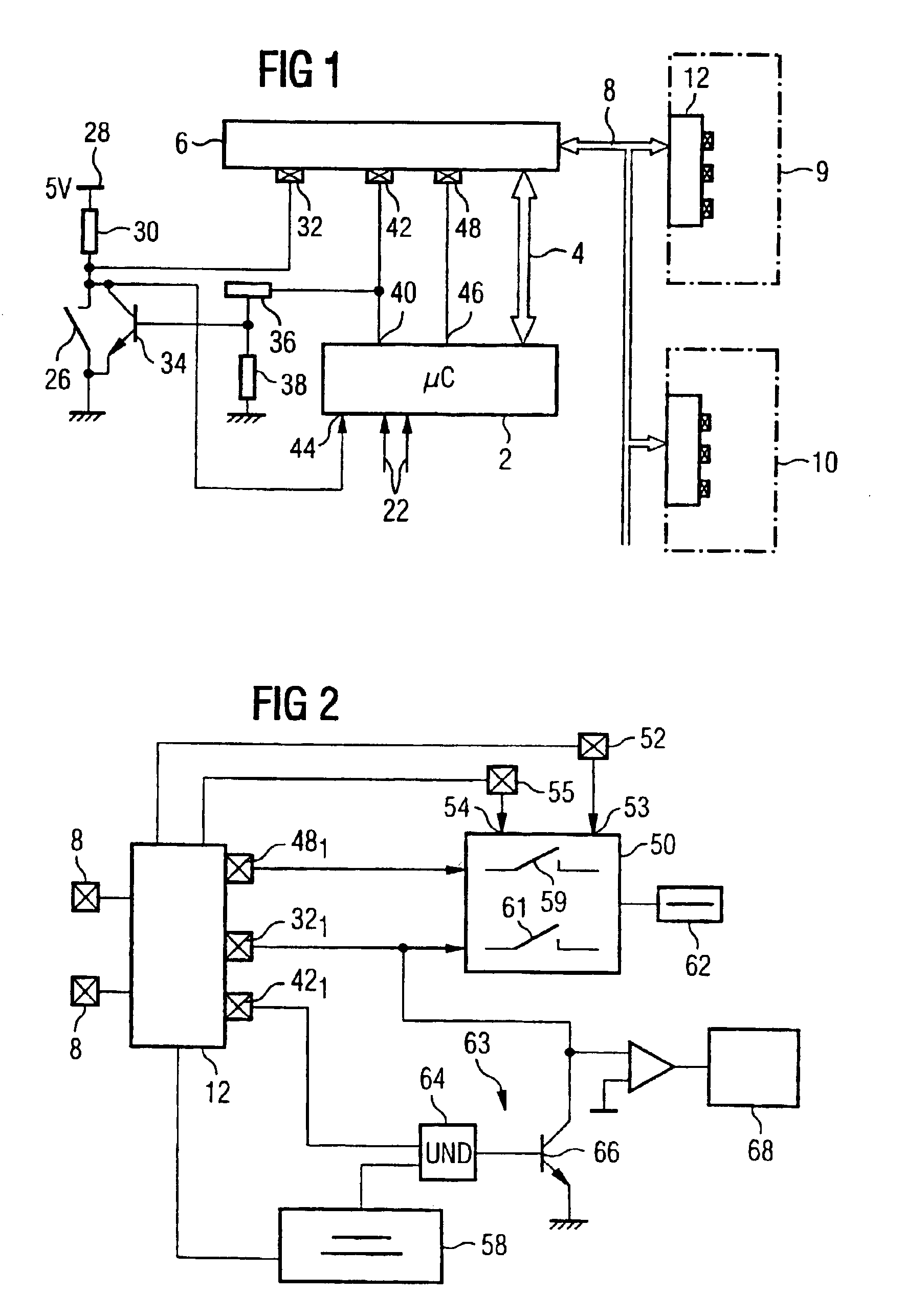
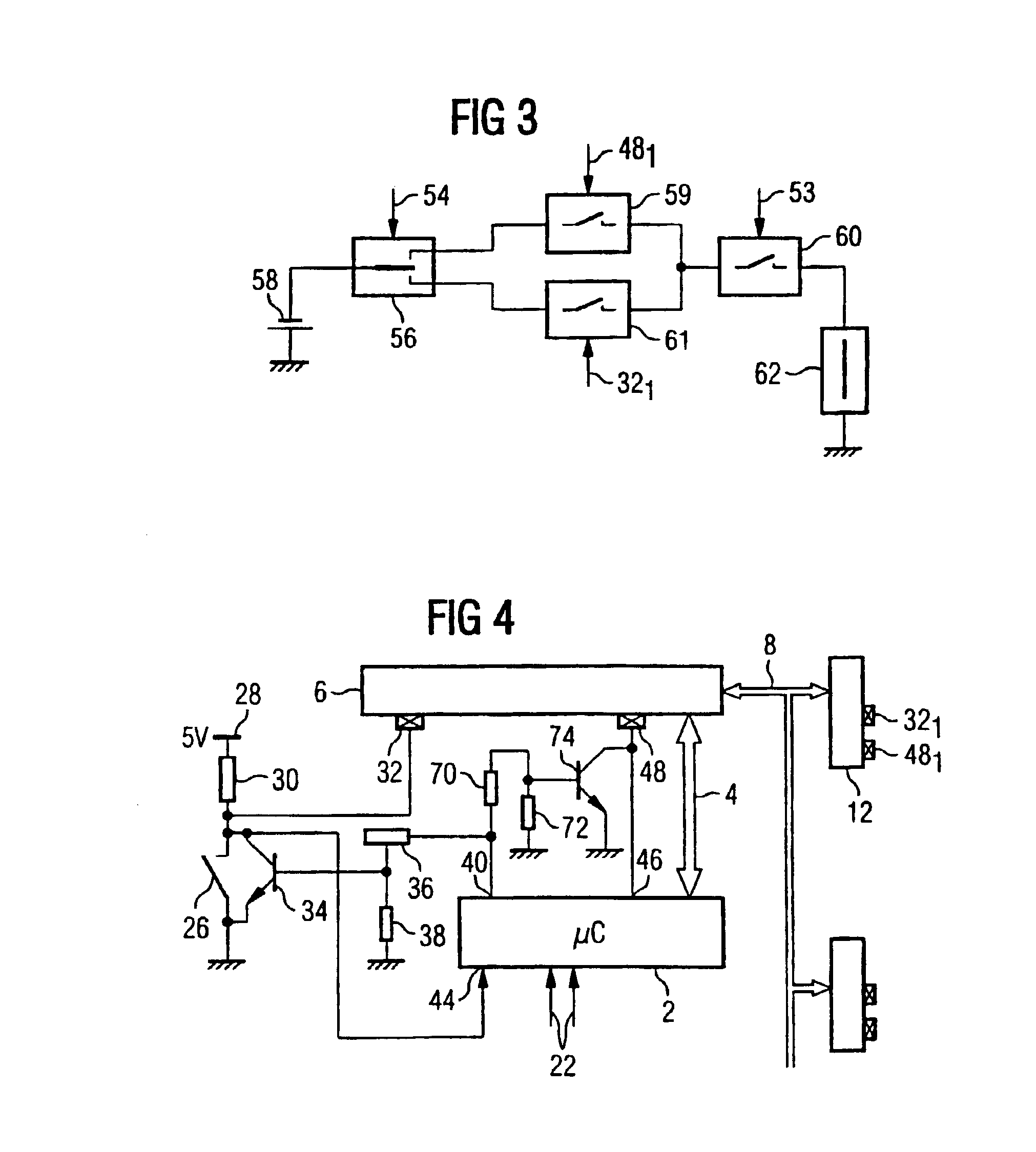
[0024]According to FIG. 1, a control device 2 of a vehicle occupant protection system is connected via a data line 4 to a communications interface 6 which is connected to firing devices 9, 10 via a communications bus 8. The firing devices are embodied as what are referred to as “smart squibbs” which have their own communications interface 12 and whose design is explained by reference to FIGS. 2 and 3. The system has a plurality of firing devices which are to be fired selectively on an individual basis or in groups in the event of a front-end impact, a side impact, a roll-over etc.

[0025]The control device 2 controls a microprocessor which has associated memories and which determines instructions and / or information from sensor input signals 22 which are generated by different acceleration sensors, said instructions and / or information being fed to the communications interface 6 via the data line 4.

[0026]In addition, a safing switch 26 which forms a redundancy switch and which closes by...


PUM


Abstract

In a data communication system, data is transmitted from a control device to a communication interface and from there via a communication bus to additional communication interfaces of trigger devices. The communication interface on the control device side has inputs, to which signals from said control device and a disarming switch can be assigned. The disarming switch can be circumvented by a bypass switch which is controlled by the control device. The state of the signal at the inputs of the communication interface on the control device side is transmitted to coresponding outputs of the communication interfaces of the triggger devices. A trigger device has a safety unit which is used to test at least one trigger unit, when the state of the signal of the outputs authorizes such a test and the trigger voltage source is not yet charged wth the full trigger voltage. In said state, the safety unit also blocks triggering as soon as the trigger voltage has been reached. The inventive system ensures a high degree of functional safety and flexibility.

Description

CLAIM FOR PRIORITY[0001]This application is a national stage of PCT / DE00 / 04410, published in the German language on Jun. 21, 2001, which claims the benefit of priority to German Application No. DE 199 60 261.1, filed on Dec. 14, 1999.TECHNICAL FIELD OF THE INVENTION[0002]The invention relates to a system for controlling the operation of modules by transmitting information from a control device via a databus, and in particular for controlling the operation of firing devices of a vehicle occupant protection apparatus in a motor vehicle. The invention also relates to a firing device for connection to the communications bus of such a system and a safety circuit for a firing device of a vehicle occupant protection system.BACKGROUND OF THE INVENTION[0003]A conventional system is disclosed in DE 197 39 808 A1. In this system, the code words which are transmitted from the control device to the communications interface contain an information section and an error-detection section which conta...

Claims


Application Information

Patent Timeline
Patent Type & Authority Patents(United States)
IPC IPC(8): B60R21/01H04L12/40B60R21/16
CPCB60R21/017H04L12/40032H04L12/403H04L12/40013B60R2021/01027H04L2012/40273
Inventor SCHMIDT, CLAUS
Owner SIEMENS AG
Why Eureka
Try Eureka