
Method for the optimization, under resource constraint, of the size of blocks of coded data

Inactive Publication Date: 2005-05-10
MITSUBISHI ELECTRIC CORP
View PDF6 Cites 28 Cited by
  • Summary
  • Abstract
  • Description
  • Claims
  • Application Information

AI Technical Summary

Benefits of technology

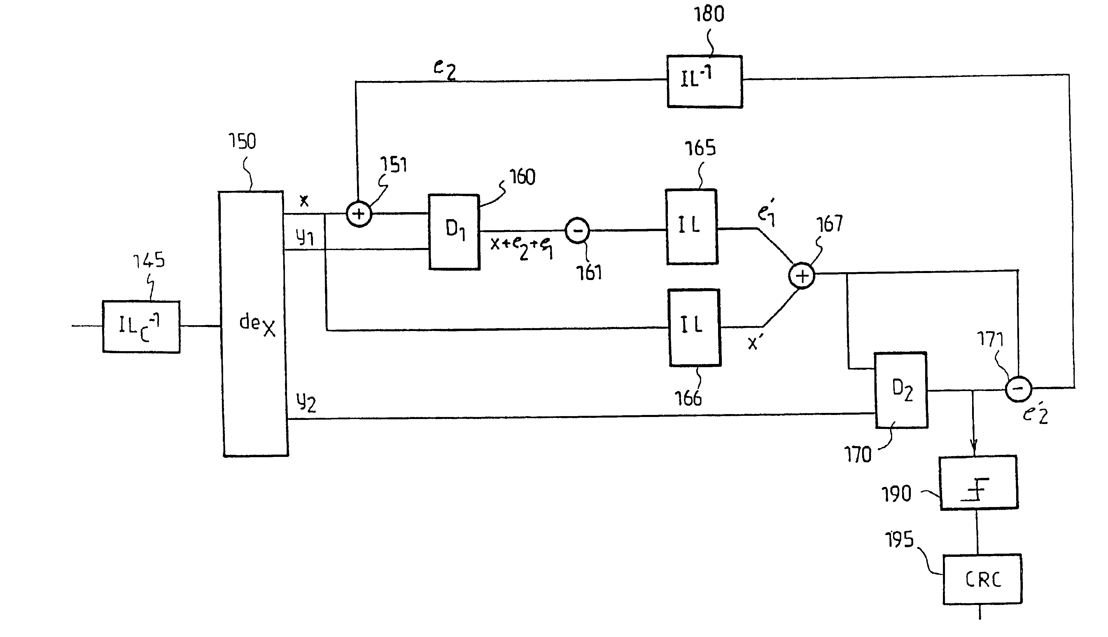
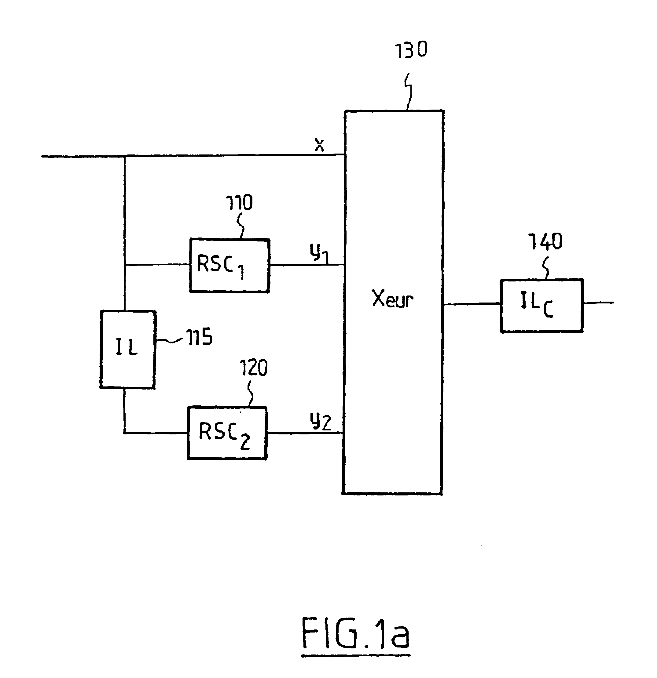
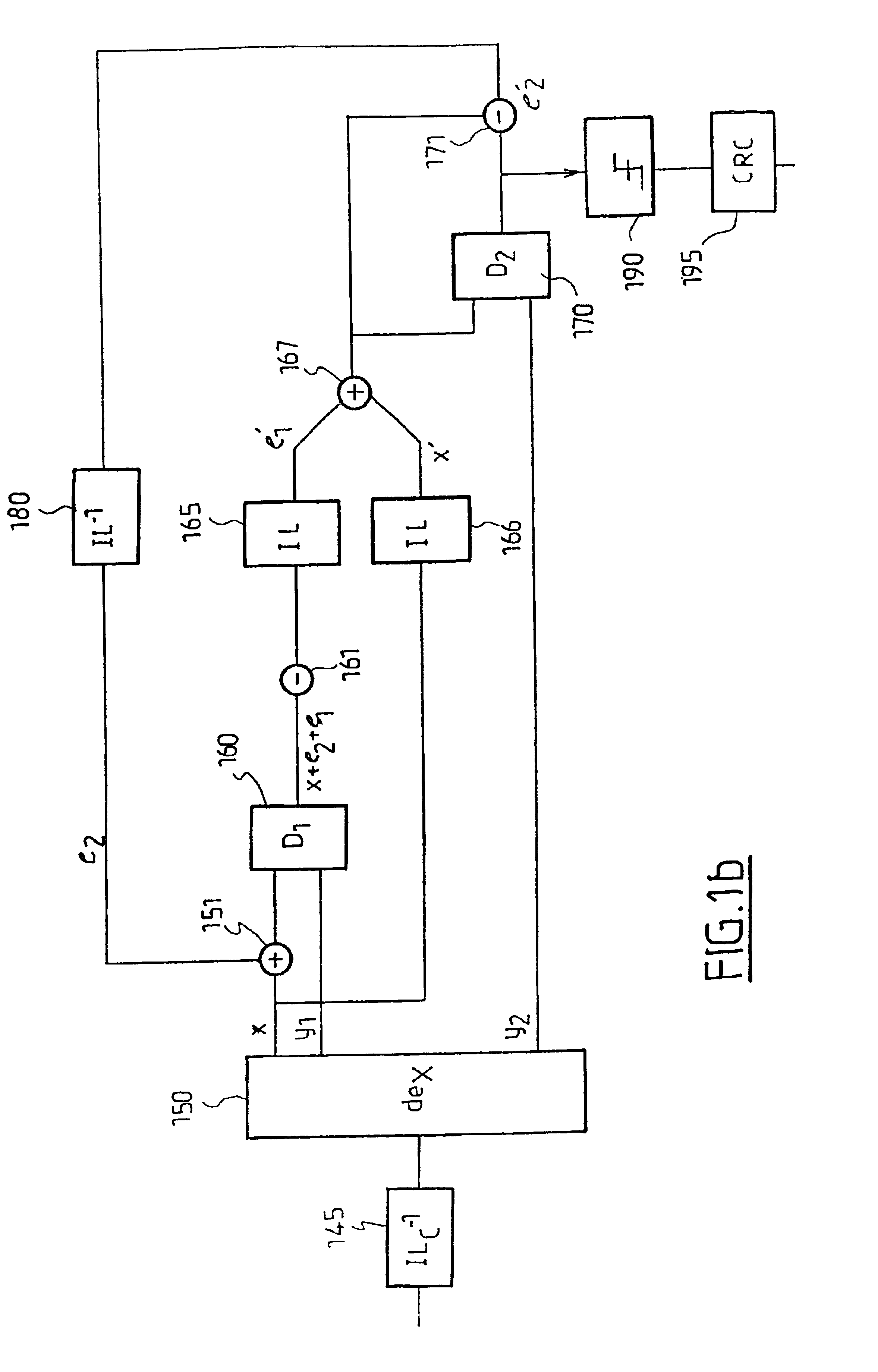
[0019]The solution afforded by the invention is defined by a method of optimising the size of coded data blocks, intended to be subjected to an iterative decoding, comprising a first step evaluating a resource available for the decoding of a block of normal size and a second step seeking, amongst a plurality of block sizes which are submultiples of the normal size by an integer factor greater than or equal to 1 and requiring on average a number of iterations compatible with the said available resource, the one which makes it possible to obtain the lowest error rate at the output of the iterative decoding.

Problems solved by technology

However, the increase in N is to the detriment of the latency of the receiver, that is to say the time at the end of which a block of data or symbols received is actually available in decoded form.
In order to regain acceptable performance, it is known that the transmission power can be increased, which naturally burdens the resources of the system.

Method used


Image

  • Method for the optimization, under resource constraint, of the size of blocks of coded data
  • Method for the optimization, under resource constraint, of the size of blocks of coded data
  • Method for the optimization, under resource constraint, of the size of blocks of coded data

Examples


first embodiment

[0056]FIG. 8 gives schematically a flow diagram for the method of optimising the block size according to the invention. The transmission depicted at 810 uses an interleaving length N. On reception, there is determined at 820, from N and from an estimation at 821 of the calculation resources and / or the maximum latency time T, the set number of iterations niterations(1) by means of equation (1). Likewise there is determined at 830, from N and the signal to noise ratio C / N, by means of a table 831, the number of iterations nreq required to reach a required level of BET or PET. Next, at 840, niterations(1) and nreq are compared. If niterations(1)≧nreq, the size of the block cannot be divided (since this would, for equal performances, result in an increase in the number of iterations) and the optimisation process is terminated. On the other hand, if niterations(1)req, there are sought at 850, in a table 851, having regard to the signal to noise ratio, all the pairs (N / k, niterations(k)),...

second embodiment

[0061]According to the invention, the process of optimising the size of the block is effected on transmission and the system does not have any return channel between the receiver and the transmitter. The algorithm does not include the estimation of the resources of the receiver but decides, for a given type of application, to improve the error rate (BET, PET) without increasing the latency time of the receiver.

[0062]When the size N of the block has been divided by a factor k, the iterative process can be effected in two possible ways.

[0063]According to a first variant, the 1st decoding iteration is effected for each of the k blocks, and then the 2nd decoding iteration is effected for the blocks with residual errors after the 1st iteration and so on until the maximum number of iterations is reached or better still until the said available resource or the time allotted for the decoding of the k blocks is exhausted. At each pass the blocks having residual errors are identified by means...


PUM


Abstract

A method of optimizing the size of blocks of coded data, intended to be subjected to iterative decoding, the method comprising a first step of evaluating a resource (T) available for the decoding of a block of normal size (N) and a second step of seeking, amongst a plurality of block sizes (N / k) which are submultiples of the normal size by an integer factor (k) greater than or equal to 1 and requiring on average a number of iterations ({overscore (n)}iterations(k)) compatible with the said available resource, the one which makes it possible to obtain the lowest error rate at the output of the iterative decoding.

Description

BACKGROUND OF THE INVENTION[0001]1. Field of Invention[0002]2. Discussion of the Related Art[0003]The present invention concerns a method of optimising the size of a block of coded data intended to be subjected to an iterative decoding, such as the one implemented in a turbodecoder or a turboequaliser. It applies in particular to the so-called third generation telecommunications systems.[0004]The concept of turbocode was introduced by C. Berrou, A. Glavieux and P. Thitimajshima in their article “Near Shannon Limit Error-Correcting Coding and Decoding: Turbo-codes”, ICC-1993, Conference Proceedings, pp. 1064-1070, and has, as is known, been subject to many developments.[0005]It will be recalled that turbocoding results from the concatenation of elementary codes separated by interleaving steps. The elementary codes can be of different types: recursive systematic codes (denoted RSC) for convolutional turbocodes or block codes (RS, BCH) for block turbocodes. The latter were described by...

Claims


Application Information

Patent Timeline
IPC IPC(8): H03M13/37H03M13/00H03M13/29G06F11/10H03M13/35H04B3/06H04L1/00
CPCH03M13/2975H03M13/6508H03M13/37
Inventor GUEGUEN, ARNAUD
Owner MITSUBISHI ELECTRIC CORP
Learn More