

Watercraft suspension
a technology for watercraft and suspension, applied in marine propulsion, special-purpose vessels, vessel construction, etc., can solve the problems of reducing the propulsion power or thrust provided by and achieve the effect of minimizing the likelihood that the jet propulsion system can be disengaged
- Summary
- Abstract
- Description
- Claims
- Application Information
AI Technical Summary
Benefits of technology
Problems solved by technology
Method used
Image

Examples
embodiment 200
[0095]FIG. 8 shows another embodiment of the internal frame assembly 220. In this embodiment, a sheet metal chassis 221 is coupled to the frame elements 206, 207, 216, and 218 through the use of mechanical fasteners or welding. The sheet metal chassis 221 replaces the frame elements 211 and 212 which were shown in the previous embodiment 200 in FIG. 7. The sheet metal chassis 221 has a main channel 222 as well as outward extensions 224. The main channel 222 functions as a seat 28 support, and the extensions 224 help to rigidify the assembly while forming gunnels 42. FIG. 8 also shows the entire triangulated forward portion of the internal frame assembly 220 and a steering assembly mounting panel 210, which is secured to the frame elements 208, 209, 216, and 218. This frame 220 is similar to a snowmobile frame.
[0096]FIG. 9 shows another embodiment of the watercraft 300 of the present invention. This embodiment of the watercraft 300 includes an internal frame assembly 230, which is a ...
embodiment 1000
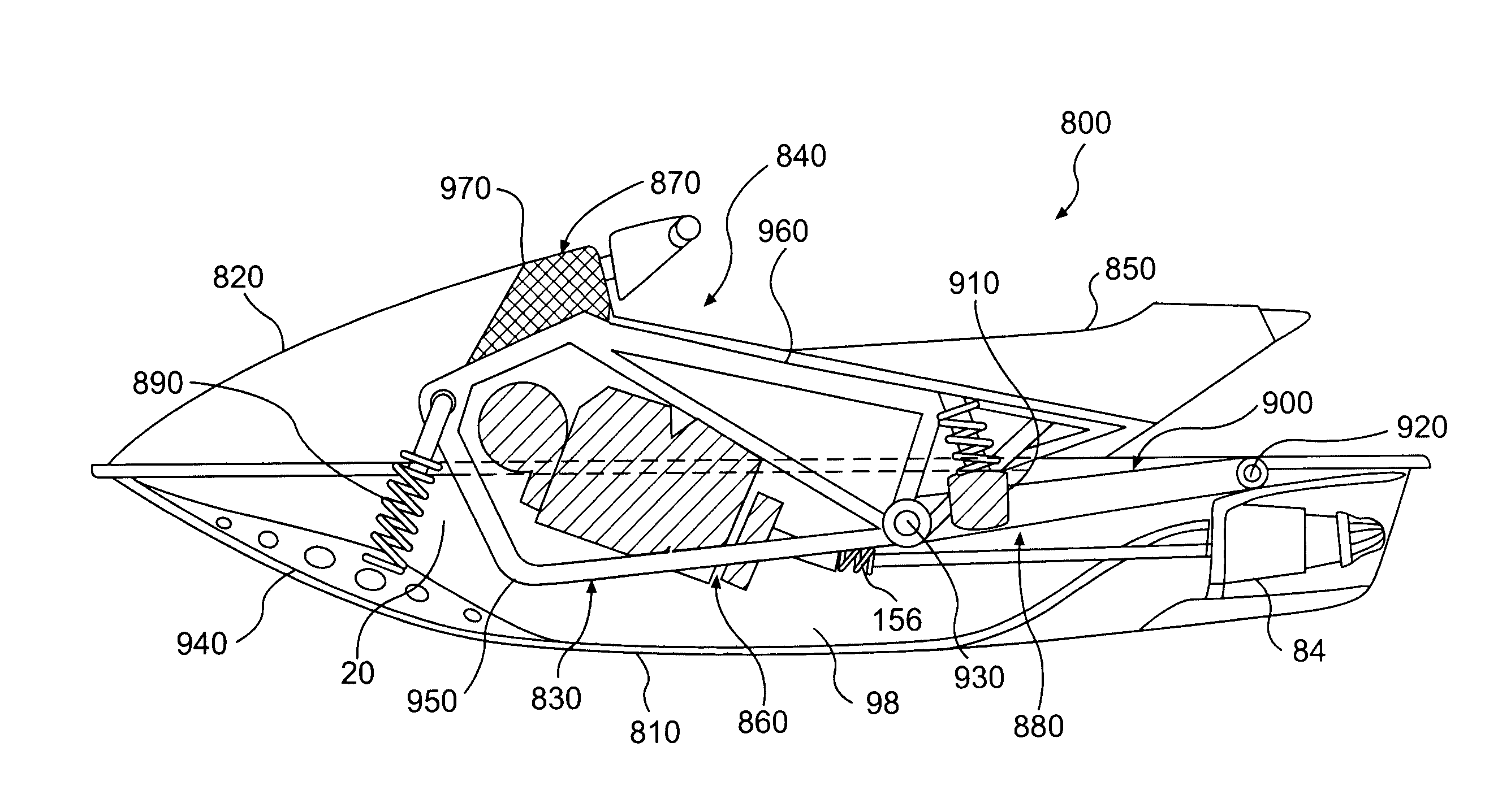
[0124]FIGS. 17 and 18 illustrate another embodiment 1000 of a watercraft of the present invention. The watercraft 1000 includes a deck 1010 and a hull 1020, and a jet propulsion assembly 1030. The deck 1010 and hull 1020 are joined together. The jet propulsion assembly 1030 connects to a rearward portion of the hull 1020 for relative pivotal movement about a laterally-extending jet propulsion assembly axis 1040. However, it is to be understood that the jet propulsion assembly 1040 could alternatively and / or additionally pivotally connect to the deck 1010 without deviating from the scope of the present invention.
[0125]A straddle-type seat 1050 and a helm assembly 1060 are supported by the deck 1010.
[0126]The jet propulsion assembly 1030 comprises a frame 1070 with a forward portion that pivotally connects to the hull 1020 at the axis 1040. A suspension element 1075 extends between the deck 1010 and the jet propulsion assembly 1030 to urge the rearward end of the jet propulsion assem...
embodiment 1300
[0130]FIGS. 19 and 19A illustrate another embodiment 1300 of a watercraft of the present invention. The watercraft 1300 includes a deck 1310 and a hull 1320. The deck 1310 and hull 1320 are movably coupled to each other via front and back suspension elements 1330, 1340. The suspension elements 1330, 1340 are preferably mounted to the deck 1310 and hull 1320 in accordance with the teachings of U.S. Pat. No. 5,603,281, FIGS. 20A and 20B and col. 8. U.S. Pat. No. 5,603,281 is incorporated by reference herein in its entirety. An engine 1350 is supported by the deck 1310 and includes a drive shaft 1360. A fuel tank 1370, battery (not shown), an oil tank (not shown), and a straddle-type seat 1370 are also supported by the deck 1310.
[0131]A lower deck portion 1380 sealingly engages the deck 1310 to define a substantially enclosed engine compartment 1390 in which the engine 1350, fuel tank 1360, battery, and oil tank are disposed. The suspension elements 1330, 1340 and engine drive shaft 13...
PUM
 Abstract
Description
Claims
Application Information