
Electrohydraulic valve controller

Inactive Publication Date: 2005-05-17
ROBERT BOSCH GMBH
View PDF8 Cites 2 Cited by
  • Summary
  • Abstract
  • Description
  • Claims
  • Application Information

AI Technical Summary

Benefits of technology

[0009]The electrohydraulic valve controller of the invention, conversely, offers the advantage that the impact speed of the valve body of the gas exchange valve on the valve seat can be reduced to a predeterminable constant value, virtually independently of any viscosity of the hydraulic medium. Because the valve brake includes a temperature compensation for the hydraulic medium, it is advantageously possible to compensate for fluctuating braking actions of the valve brake that are caused by temperature-dictated changes in viscosity. As a result, the impact speed of the valve body of the gas exchange valve can be set to a predeterminable value independently of any fluctuations in temperature. In particular, an automatic mechanical temperature compensation is possible as a result.

Problems solved by technology

The result is on the one hand noise, and on the other the valve components are subject to relatively high wear.
A disadvantage, however, is that the braking action of the valve brake is very highly dependent on the viscosity of the hydraulic medium, which as a rule is hydraulic oil.
As a result, the valve action of the valve brake and thus the impact speed of the valve body on the valve seat ring is highly temperature-dependent.

Method used


Image

  • Electrohydraulic valve controller
  • Electrohydraulic valve controller
  • Electrohydraulic valve controller

Examples


Embodiment Construction

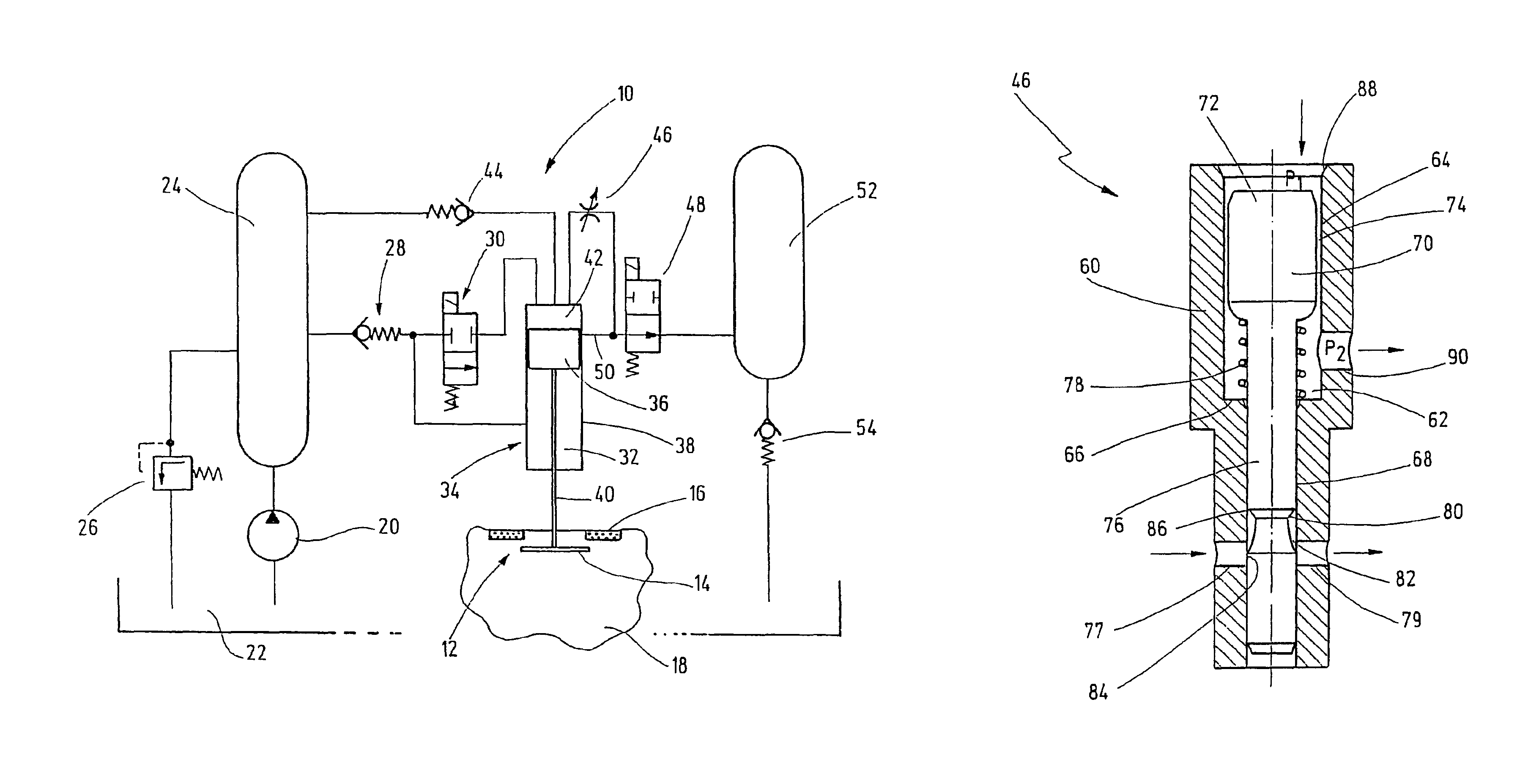
[0014]FIG. 1 shows a circuit diagram of an electrohydraulic valve controller 10 for controlling a gas exchange valve 12. The gas exchange valve 12 includes a valve body 14, with which a valve seat embodied as a valve seat ring 16 is associated. The valve seat ring 16 is disposed in a cylinder head 18, shown here only in suggested form, of an internal combustion engine. The structure and mode of operation of such gas exchange valves 12 are well known and therefore need not be addressed in detail in the context of the present description.

[0015]The valve controller 10 includes a hydraulic pumping device 20, by means of which a hydraulic medium—hereinafter called hydraulic oil—can be pumped out of an oil sump 22 into a high-pressure reservoir 24. The high-pressure reservoir 24 communicates with the oil sump 22 via a pressure limiting valve 26, so that a defined oil pressure can be built up in the high-pressure reservoir 24.

[0016]The high-pressure reservoir 24 moreover communicates via a...


PUM


Abstract

The invention relates to an electrohydraulic valve controller for controlling a gas exchange valve in internal combustion engines, having a hydraulically actuatable control valve including a control valve piston which can be acted upon, via electrically actuatable valves, by a hydraulic medium that is under pressure, and a hydraulically acting valve brake is assigned to the control valve piston. The valve brake (46) includes a temperature compensation for the hydraulic medium.

Description

CROSS-REFERENCE TO RELATED APPLICATIONS[0001]This application is a 35 USC 371 application of PCT / DE 02 / 01806 filed on May 18, 2002.BACKGROUND OF THE INVENTION[0002]1. Field of the Invention[0003]The invention relates to an improved electrohydraulic valve controller, in particular for controlling a gas exchange valve in internal combustion engines.[0004]2. Prior Art[0005]In internal combustion engines used for driving motor vehicles a fuel-air mixture is compressed and ignited in a work chamber where the energy produced is converted into mechanical work. In such engines, the air, or the fuel-air mixture, is delivered to the work chamber via valves (inlet or intake valves) and to remove the products of combustion from the work chamber via valves (outlet or exhaust valves). Controlling these valves is very significant for determining the efficiency of the engine. In particular, the gas exchange in the work chamber is controlled via the control of the valves.[0006]Besides camshaft contr...

Claims


Application Information

Patent Timeline
IPC IPC(8): F01L9/02F01L9/00F01L9/10
CPCF01L9/02F01L2820/02F01L9/10
Inventor DIEHL, UDOHAMMER, UWEBEUCHE, VOLKERLANG, PETERREIMER, STEFAN
Owner ROBERT BOSCH GMBH
Features
  • Generate Ideas
  • Intellectual Property
  • Life Sciences
  • Materials
  • Tech Scout
  • Unparalleled Data Quality
  • Higher Quality Content
  • 60% Fewer Hallucinations
Learn More