
Rotary piston engine and method of operation

a rotary piston engine and rotary piston technology, applied in the direction of rotary piston liquid engines, machines/engines, liquid fuel engines, etc., can solve the problems of not developing a commercially viable rotary engine design, heavy turbocharger, and failure to perform well at altitude, so as to achieve high torque, high horsepower, and high fuel efficiency

Inactive Publication Date: 2005-05-17
ALTERNATIVE POWER
View PDF14 Cites 29 Cited by
  • Summary
  • Abstract
  • Description
  • Claims
  • Application Information

AI Technical Summary

Benefits of technology

[0024]Another object of a preferred embodiment of the present invention is to provide an improved direct injection rotary engine design and method of operation.
[0056]In another embodiment, the invention comprises a rotary piston internal combustion engine that comprises direct fuel injection with variable injector timing, to achieve fully stratified charge, at high air fuel ratios (preferably in excess of about 20:1), resulting in high fuel efficiency, while also achieving high horsepower and high torque over a wide range of engine rpm, and resulting in fewer hydrocarbon and reduced NOx emissions.

Problems solved by technology

Various inefficiencies in these designs, however, led to their abandonment after the First World War.
Curtiss-Wright, however, did not develop a commercially viable rotary engine design.
Nonetheless, this design required a heavy turbocharger and did not perform well at altitude.
(The low atmospheric pressures impaired the turbocharger's performance.)
With the exception of Mazda, each has tried and failed to achieve a commercially successful rotary engine design.
Although some prior workers recognized that the rotor spins at a different speed than the crankshaft, these prior workers apparently failed to account for this difference in rotation speeds by adjusting the timing of fuel injection and ignition as a function of engine speed.
Prior designs have failed, apparently, to account for the effect of these differences on engine injection and ignition timing at different engine rpms.
If injection occurs too early in the cycle, when air flow is not sufficiently turbulent, the fuel is not properly atomized and dispersed.
If too late, the face of the piston at its trailing edge is wetted by fuel or fuel is distributed between the trailing edge of one combustion chamber and the leading edge of the next, resulting in loss of efficiency and power.
In 1992, King reported that “[i]n general rotary combustion engines have not been able to achieve brake thermal efficiencies as high as that of reciprocating engines.
Both these factors increase the amount of heat energy lost during combustion.
The large surface area-to-volume ratio (a result of the long rectangular shaped chamber) also increases the time required to burn the mixture since the flame has farther to burn and increases the amount of unburned end gas in the combustion chamber.
This will keep the initial burning rate high due to a rich local mixture around the spark plugs and eliminate the unburned gas near the edges of the chamber.” The solution adopted by King, however, failed to resolve these issues.
Further, the present design and method have achieved superior performance under conditions of air to fuel ratio that are considered to be so lean (from about 20:1 to about 60:1) that prior known designs would fail to perform.
Further, the cost of the invention is unexpectedly low relative to prior known designs.

Method used


Image

  • Rotary piston engine and method of operation
  • Rotary piston engine and method of operation
  • Rotary piston engine and method of operation

Examples


example

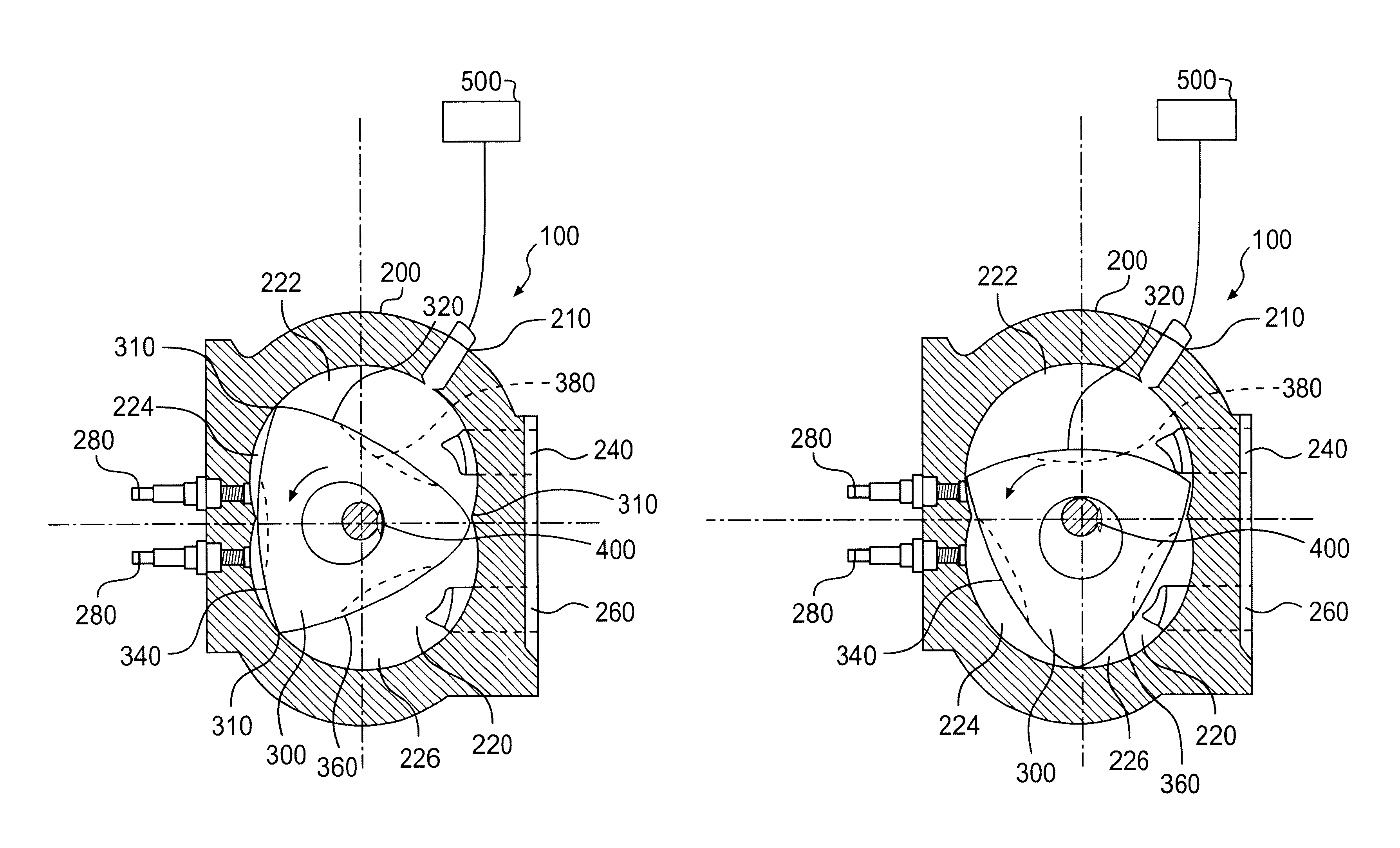
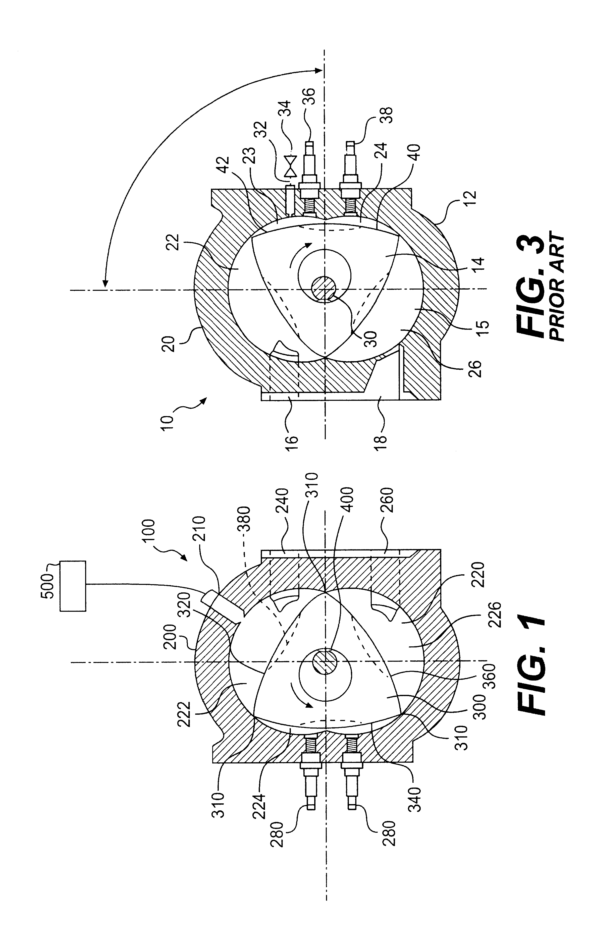
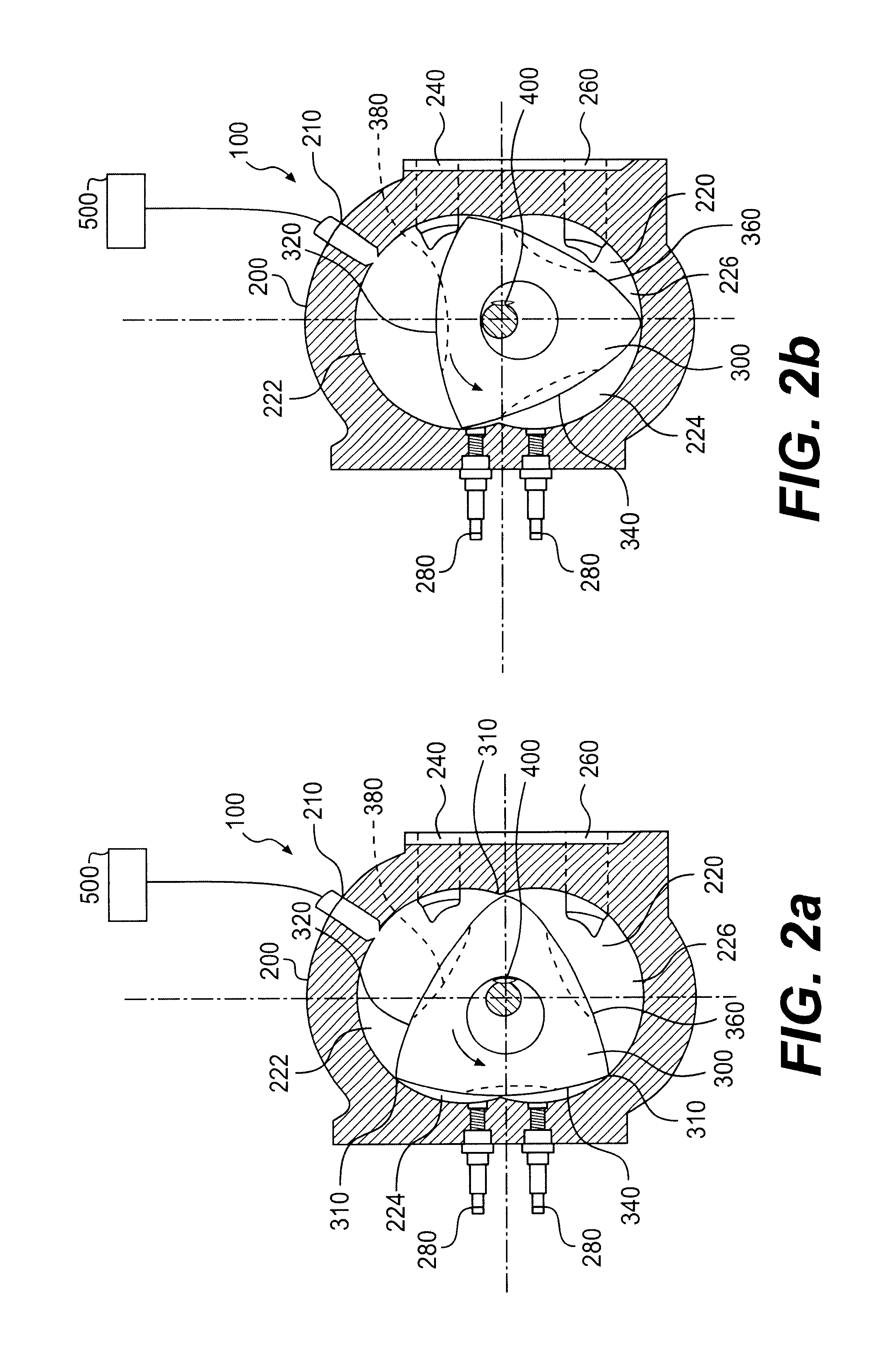
[0085]A single rotor of the type known prior to the present invention is managed using the method of the present invention to obtain superior performance. At 5,000 rpm, the rotorwill subtend 30 degrees of crankshaft angle per millisecond, if the injector port remains open. (5,000 rpm×0.006=30° per ms.) The intake timing, as shown in FIG. 4a, is typically 270°. The injection cycle, therefore, cannot be longer than 9 milliseconds (270° divided by 30°=9 ms.) The present invention preferably keeps the injector event within that window and, further, preferably as short as possible (for example, 2-4 ms.) This is accomplished by either further advancing the injector timing to maintain it within the intake window and / or shortening the pulse width of the injector event in order to maintain the injector event at the proper point in the cycle. Prior known methods of managing direct injected rotary engines have not disclosed and appear not to have recognized these features of the present invent...


PUM


Abstract

The present invention relates to a design and method of operation of an improved rotary piston engine. In particular, a preferred embodiment of the present invention is directed to a rotary engine with improved reliability, comprising a housing, having side portions and a peripheral portion defining a chamber, a rotor, disposed within the chamber, and at least one exhaust port in one of the side portions.

Description

CROSS REFERENCE TO RELATED APPLICATIONS[0001]The present invention relates to and claims priority on U.S. Provisional Application Ser. No. 60 / 235,564, filed on Sep. 27, 2000.FIELD OF THE INVENTION[0002]The present invention relates to a design and method of operation of an improved rotary piston engine. The engine of the present invention achieves higher performance (high torque and high horsepower), higher fuel efficiency, and lower emissions, in a lighter weight engine package, relative to prior known engines and methods of internal combustion engine management. The engine and method of the present invention are applicable to a wide variety of fuels and applications, including but not limited to automotive, racing, supplemental power, and various industrial uses. In particular, the invention may include any one or more of the following enhancements or features: side port exhaust; direct fuel injection; fully stratified charge; variable fuel injector timing; and various ignition an...

Claims


Application Information

Patent Timeline
Patent Type & Authority Patents(United States)
IPC IPC(8): F01C1/22F01C1/00F02B75/12F02B75/00F02B75/02F02B53/00
CPCF01C1/22F02B53/00Y02T10/123F02B2075/027F02B2075/125F02B2053/005Y02T10/12
Inventor BARRETT, ERIC
Owner ALTERNATIVE POWER
Learn More