Front body structure for vehicle

a front body and vehicle technology, applied in the direction of roofs, vehicle arrangements, transportation and packaging, etc., can solve the problems of difficult to achieve the load characteristics allowing continuous absorption of collision energy, and the weight of the vehicle body to be increased remarkably, so as to achieve effective energy absorption

Inactive Publication Date: 2005-05-17
NISSAN MOTOR CO LTD
View PDF33 Cites 40 Cited by
  • Summary
  • Abstract
  • Description
  • Claims
  • Application Information

AI Technical Summary

Benefits of technology

[0003]The above-mentioned front body structure can perform the absorption of energy effectively against a collision load inputted to the side member in the axial direction. However, if a collision load is applied on the side member obliquely from the front, then the front part of the side member is apt to be folded from its root.
[0006]In such a situation, it is an object of the present invention to provide a front body structure that could collapse a front end of the side member in the axial direction certainly even if the collision load were exerted on the side member from its front in any direction (including an oblique direction), thereby enhancing the absorbing efficiency of the collision energy.

Problems solved by technology

Nevertheless, by this front body structure, it is difficult to attain a load characteristics allowing of continuous absorption of the collision energy due to the axial collapse of the side member.
However, there is the possibility of causing the weight of a vehicle body to be increased remarkably.

Method used


Image

  • Front body structure for vehicle
  • Front body structure for vehicle
  • Front body structure for vehicle

Examples


first embodiment

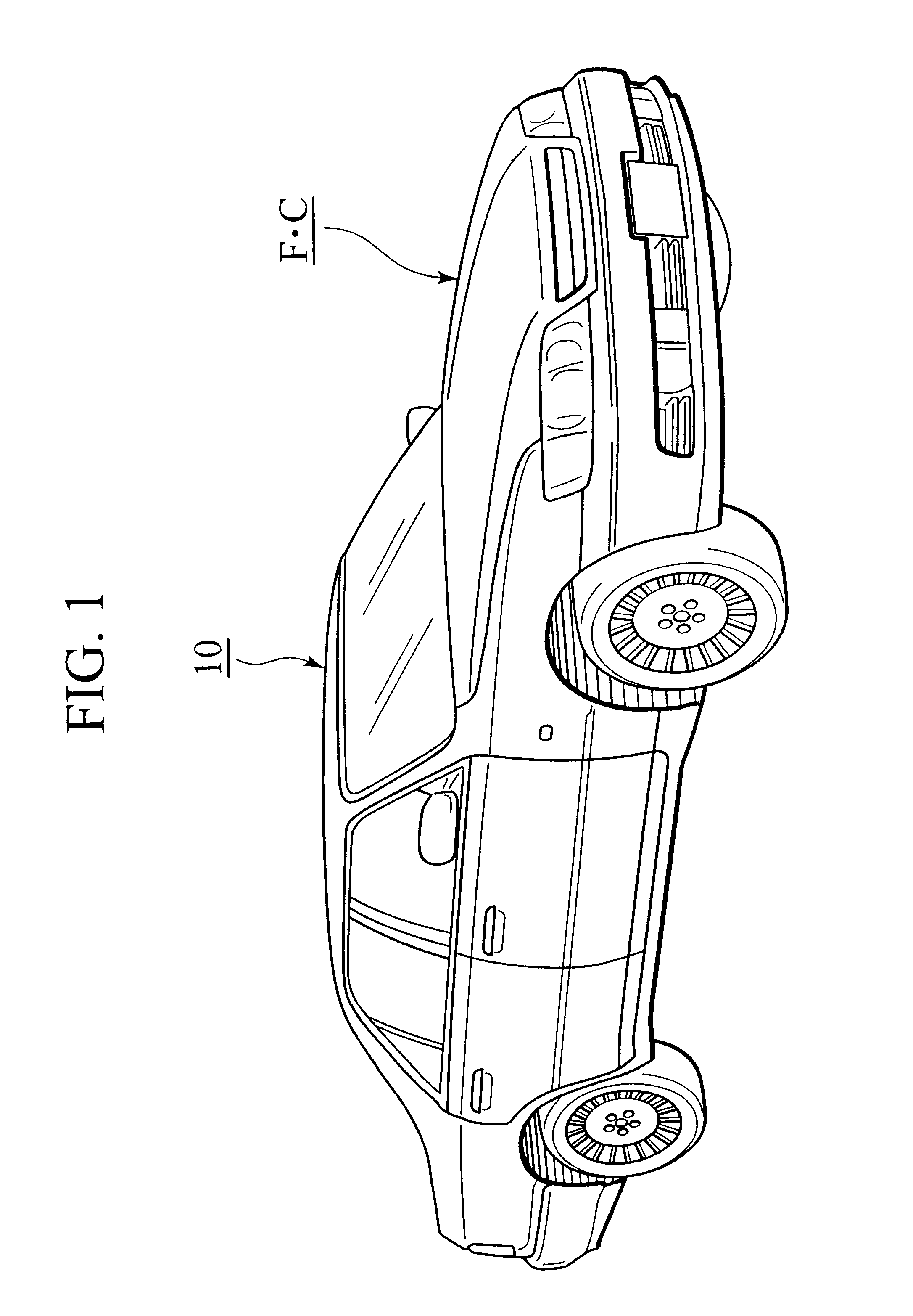
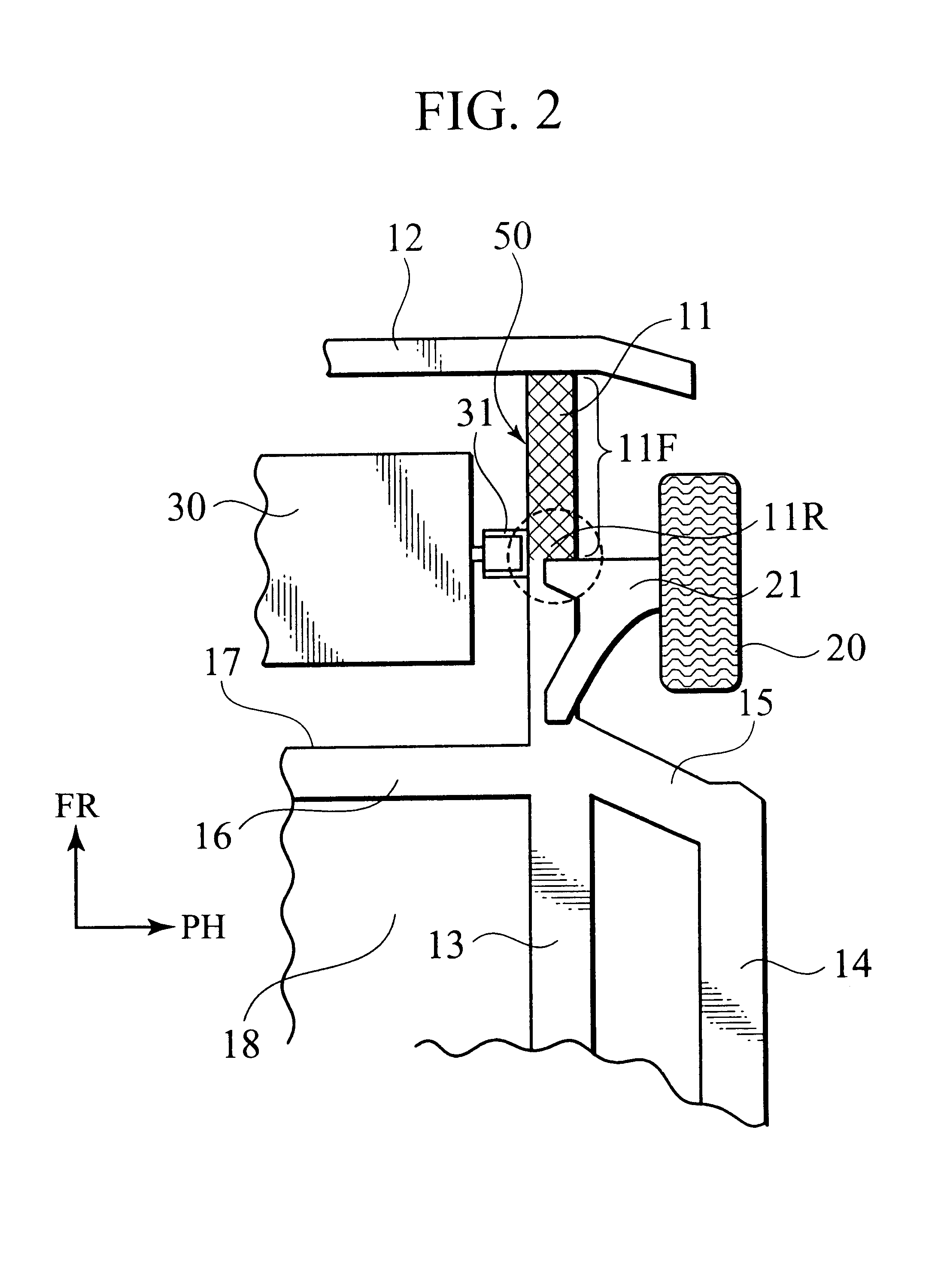
[0057]FIGS. 1 to 10 show the front body structure in accordance with the present invention. The front body structure of the embodiment is applicable to a front compartment FC of a vehicle body 10 of FIG. 1. As representatively shown in FIG. 2, the front body structure includes a pair of side members (only one shown) 11 arranged on both (left-and-right) sides of the vehicle body 10 to extend in the fore-and-aft direction of the vehicle straight. The side members 11 are parallel with each other and have their front ends joined to a bumper reinforcement 12 forming a framework of a not-shown bumper.

[0058]Behind each side member 11, an extension side member 13 is formed in succession so as to extend from a dash panel 17 to the underside of a floor panel 18. Outside the side members 11 in the width direction of the vehicle, a pair of side sills 14 are arranged so as to be substantially parallel with the side members 11. On each side of the vehicle, the front end of the extension side memb...

second embodiment

[0082]Then, the rigidity of the reinforcement part 11R mounting the power unit 30 (see FIG. 2) thereon can be ensured by the plate thickness t5 of the partition 61e. In the second embodiment, a plate thickness t of the circumferential wall of the side member 11 is established to be constant over the whole sections of the forward area 11F.

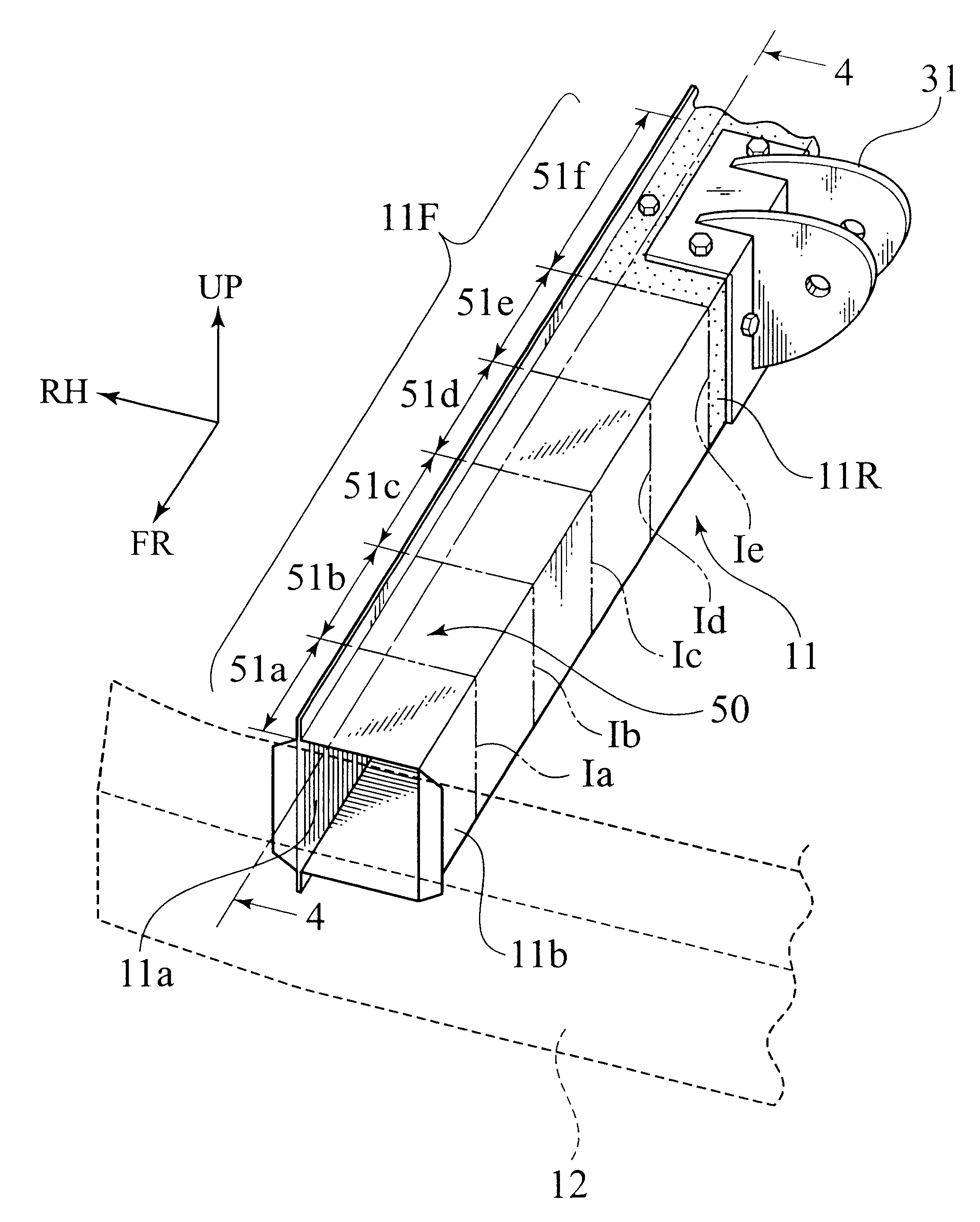
[0083]Therefore, according to the second embodiment of the invention, the maximum stress generated in the imaginary sections succeeding in the longitudinal direction of the forward area 11F when the collision load F is applied to the front end of the side member 11, can be controlled by the formation of the partitions 61a, 61b, 61c, 61d, 61e. Thus, the variable. partition-thickness structure 60 facilitates the adjustment of balance in strength, whereby the collapse K at the collision can be induced from the front end of the forward area 11F certainly, effecting the similar effects to the first embodiment.

[0084]Although the plate thickness t of the c...

fourth embodiment

[0095] the strength adjusting mechanism is formed by a variable sectional-dimension structure 70 where sectional dimensions x, y defining the forward area 11F gradually change in the longitudinal direction of the side member 11, as shown in FIG. 14.

[0096]In addition, the variable sectional-dimension structure 70 is formed so that, in the forward area 11F of the side member 11, a plate thickness t tapers off to its front end, as shown in FIG. 15. That is, in the forward area 11F, all of the sectional dimensions x, y and the plate thickness t changes in the longitudinal direction of the side member 11 continuously.

[0097]In this embodiment, the side member 11 is formed by an extrusion of light metals, such as aluminum alloy, providing the forward area 11F with the above variables x, y, t.

[0098]Also in this embodiment, there is established a condition that, when the collision load F is applied to the front end of the side member 11 statically, the maximum value {see the expression (1)} ...


PUM


Abstract

A front body structure includes a pair of side members 11 and a strength adjusting mechanism 50 arranged on a forward area 11F of each side member 11. By the strength adjusting mechanism 50, it is established that a maximum stress generated in a front part of each one of imaginary sections Ia-Ie continuing in the longitudinal direction of the forward area 11F becomes more than or close to a maximum stress generated in a rear part of the each one of imaginary sections. As a result, when the collision load is inputted to the front end of the side member 11 obliquely from the front, a collapse is induced from the front end of the forward area 11F toward the rear. Then, the collapse is transmitted to the rear part of the area 11F continuously, enhancing the absorbing efficiency of the collision energy.

Description

BACKGROUND OF THE INVENTION[0001]The present invention relates to a front body structure for a vehicle. Japanese Patent Application Laid-open No. 2001-158377 discloses one front body structure for a vehicle, which is designed so as to absorb collision energy by axially collapsing side members on the front side of the vehicle.[0002]In the front body structure, the side members are shaped to have polygonal sections respectively. For purposes of absorption of the collision energy, each side member is provided, on its front wall, with a bead which promotes an axial collapse of the side member when an axial input acts on the side member.SUMMARY OF THE INVENTION[0003]The above-mentioned front body structure can perform the absorption of energy effectively against a collision load inputted to the side member in the axial direction. However, if a collision load is applied on the side member obliquely from the front, then the front part of the side member is apt to be folded from its root.[0...

Claims


Application Information

Patent Timeline
Patent Type & Authority Patents(United States)
IPC IPC(8): B62D21/15
CPCB62D21/152
Inventor SAEKI, HIDETSUGU
Owner NISSAN MOTOR CO LTD
Why Eureka
Try Eureka