Projection type image display apparatus
a projection type and image display technology, applied in the field of projection devices, can solve the problems of black image contrast deterioration, performance decline, and unsatisfactory effect of quarter-wave plates, and achieve the effects of high contrast, high resolution, and satisfactory image quality performances
- Summary
- Abstract
- Description
- Claims
- Application Information
AI Technical Summary
Benefits of technology
Problems solved by technology
Method used
Image
Examples
second embodiment
[0038]Next, the invention will be described referring to FIG. 3.
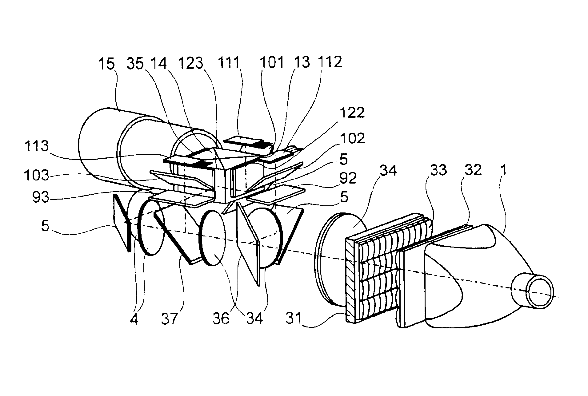
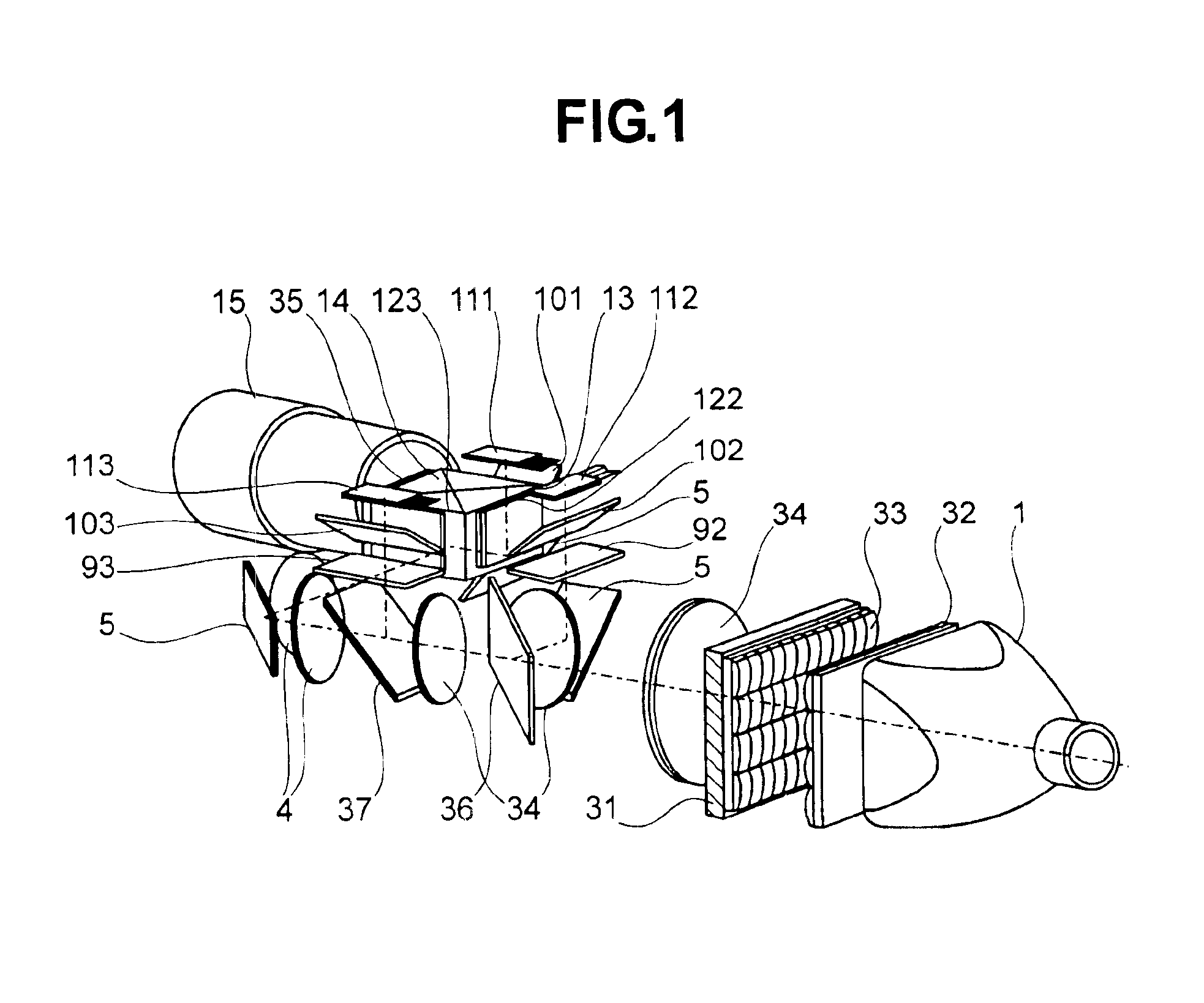
[0039]The portion from the lamp unit 1 to the collimator lens 34 is the same as in the embodiment shown in FIG. 1 except that the first lens array and the second lens array have horizontally long cells and a polarization converter 31 is disposed in a way to match vertical pitches and the light path is bent approximately 90 degrees by the reflection mirror 5.
[0040]Light is separated into R (red), G (green), and B (blue) light by dichroic mirrors 6 and 7. Then, B light rays are bent 90 degrees by a B-reflection mirror 17. R, G, and B light respectively pass through R, G, and B light auxiliary polarizers 91, 92, 93, then through R, G, and B light reflection polarizing plates 101, 102, 103 and respectively reach R, G, and B light reflection liquid crystal panels 111, 112, 113. The rays reflected by the R, G, and B light reflection liquid crystal panels are reflected and bent 90 degrees by the R, G, and B light reflection po...
third embodiment
[0049]FIG. 4 shows the present invention. The structure is the same as that of the embodiment illustrated in FIG. 3 except the following points. The reflection polarizing plates 10, reflection liquid crystal panels 11 and auxiliary analyzers 9 are located on the surface of the hermetically sealed chassis 42 which borders on the outside. Because the hermetically sealed chassis 42 are dustproof, they prevent dust adhesion on the reflection polarizing plates 10, reflection liquid crystal panels 11, etc., so that on-screen image missing or image quality deterioration may not occur. The use of optical components such as the reflection polarizing plates 10 and auxiliary analyzers 9 as boundaries assures air tightness without interfering with the light paths. Hermetic seals are placed between the optical components and the chassis 42 to assure air tightness. A cooling fan cools the auxiliary analyzers. Only the rear sides of the reflection liquid crystal panels 11 are exposed to the outsid...
fourth embodiment
[0050]FIG. 5 shows the present invention. The structure is the same as that of the embodiment illustrated in FIG. 3 except the following points. A color separation system separates light into R, G and B light, which pass through the auxiliary analyzers 91, 92, and 93 and through the reflection polarizing plates 10 and reach the reflection liquid crystal panels 11. The image light modulated and reflected by the reflection liquid crystal panels 11 is reflected by the reflection polarizing plates 10 before entering a color combining prism 14. A hermetically sealed chassis 42 houses the reflection polarizing plates 10, reflection liquid crystal panels 11, cross dichroic prism 14 and auxiliary analyzers 9 and has auxiliary polarizers 9 on its boundaries. A cooling fan cools the auxiliary analyzers 9.
[0051]Alternatively, the reflection polarizing plates 10, reflection liquid crystal panels 11, cross dichroic prism 14 and quarter-wave plates 9 may be located on the boundaries of the hermet...
PUM
| Property | Measurement | Unit |
|---|---|---|
| aspect ratio | aaaaa | aaaaa |
| angle | aaaaa | aaaaa |
| angle | aaaaa | aaaaa |
Abstract
Description
Claims
Application Information
 - R&D
- Intellectual Property
- Life Sciences
- Materials
- Tech Scout
- Unparalleled Data Quality
- Higher Quality Content
- 60% Fewer Hallucinations
Browse by: Latest US Patents, China's latest patents, Technical Efficacy Thesaurus, Application Domain, Technology Topic, Popular Technical Reports.
© 2025 PatSnap. All rights reserved.Legal|Privacy policy|Modern Slavery Act Transparency Statement|Sitemap|About US| Contact US: help@patsnap.com


