Ring gear machine clearance

a technology of ring gear machine and ring gear pump, which is applied in the direction of rotary piston engine, rotary or oscillating piston engine, portable lifting, etc., can solve the problems of large tangential clearance cost, large radial clearance, and difficulty in toothing, so as to improve volumetric efficiency and reduce noise from running s

Inactive Publication Date: 2005-05-17
EISENMANN SIEGFRIED A +1
View PDF18 Cites 8 Cited by
  • Summary
  • Abstract
  • Description
  • Claims
  • Application Information

AI Technical Summary

Benefits of technology

[0007]It is an object of the invention to configure meshing toothings of an internal-axis running set of a ring gear machine such that the volumetric efficiency is improved and the noise developed by the running set is reduced. At the same time, the toothings are intended to be based on a simple mathematical specification for generating them.

Problems solved by technology

Apart from this, mechanical noise materializes due to discontinuous locations.
Although this permits adjustment of a radial clearance while avoiding discontinuous locations, this is at the cost of a tangential clearance larger than the radial clearance, due to the specification in generating the epicycloids and hypocycloids.
At the point of full mesh, the gap formed between the toothings from the vertex of the mating tip to the flanks of the corresponding tooth is thus widened, resulting in the toothing being problematic.
An excessive backlash circumferentially results in chatter circumferentially in the region of the rolling circle because of hydraulic and dynamic forces prompting a change in flank contact.
If the tangential clearance is excessive, the fluid film between the slide-rolling flanks of the gear is too thick and the shock caused by the change in flank contact is thus inadequately dampened.
Furthermore, increasing the clearance in the direction of the flanks is detrimental to the volumetric efficiency of the ring gear machine.

Method used


Image

  • Ring gear machine clearance
  • Ring gear machine clearance
  • Ring gear machine clearance

Examples


Embodiment Construction

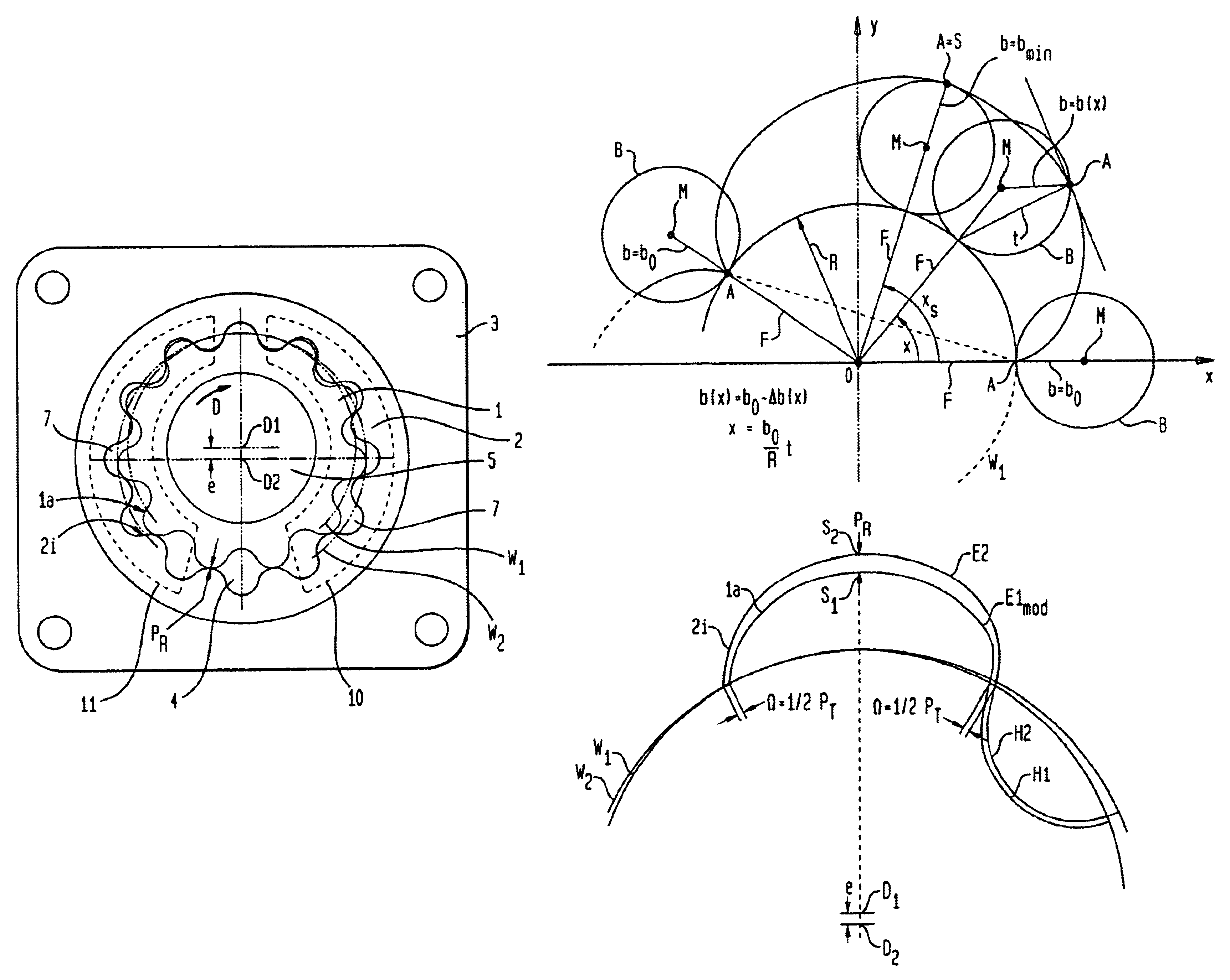
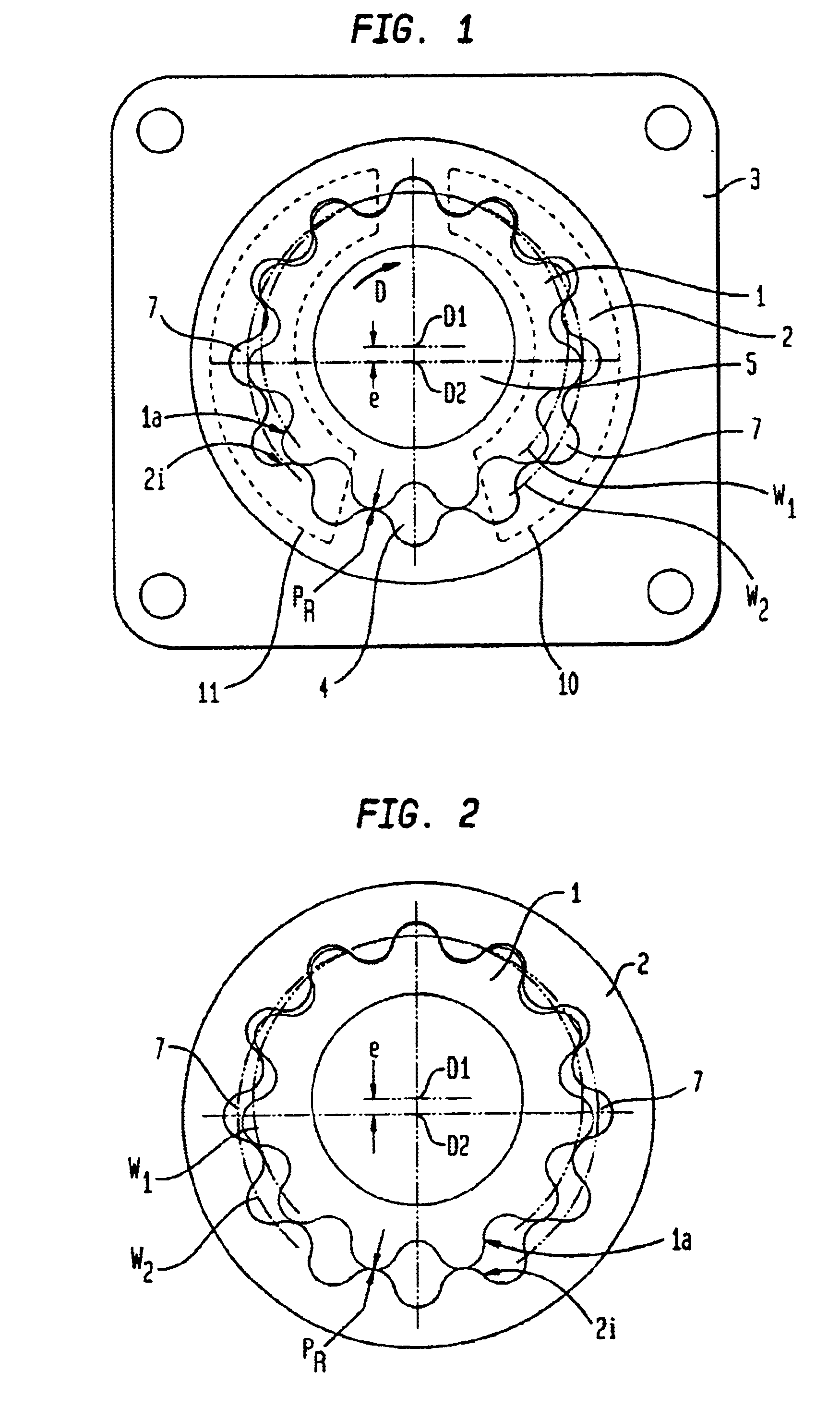
[0048]FIG. 1 shows a ring gear pump in a view perpendicular to a running set which is rotationally mounted in a gear chamber 4 of a pump casing 3. A cover of the pump casing 3 is omitted to expose the gear chamber 4 with the running set. The running set of the ring gear pump is shown again by itself in FIG. 2.

[0049]The ring gear pump comprises an internal gear 1 with an external toothing 1a and an external gear 2 with an internal toothing 2i which forms the running set. The external toothing 1a has one tooth less than the internal toothing 2i. Regarding the internal-axis running set, it is to be noted generally that the number of teeth of the internal toothing 2i is preferably at least four and preferably not more than 15, and more preferably at least five. In the example embodiment, the internal toothing 2i has twelve teeth.

[0050]An axis of rotation D1 of the internal gear 1 runs parallel to and spaced away from, i.e. eccentric to, an axis of rotation D2 of the external gear 2. Thi...


PUM


Abstract

A displacement-type ring gear machine includes a casing including a gear chamber comprising a supply port and a discharge port, an internal gear accommodated in the gear chamber and comprising an external toothing, and an external gear eccentric to the internal gear and comprising an internal toothing meshing with the external toothing so as to form expanding and contracting fluid cells which direct the working fluid from the supply port to the discharge port. The meshing toothings comprise a radial clearance and a tangential clearance which is smaller than the radial clearance. The tips or roots of at least one of the two toothings comprise a profile derived from a cycloid. The profile of the tips and roots of the at least one of the toothings is formed by or from the locus of a point on the circumference of a pitch circle rolling on a fixed circle, the radius of the pitch circle becoming continuously smaller from the two flank portions to the vertex portion in the case of the tips and becomes continuously larger or continuously smaller in the case of the roots.

Description

FIELD OF THE INVENTION[0001]The invention relates to the clearance of displacement-type ring gear pump and motor running sets.BACKGROUND OF THE INVENTION[0002]Ring gear pumps compress a working fluid in delivering it from a low-pressure side to a high-pressure side whilst ring gear motors are powered by compressed working fluid supplied at a high-pressure side and discharged at a low-pressure side of the ring gear motor. Both kinds of ring gear machine include a running set comprising an internal spur gear with an external toothing and an external spur gear with an internal toothing. The internal toothing generally features one tooth more than the external toothing. The two toothings are meshed. When one gear is rotated relative to the other, circulating, expanding and contracting fluid cells materialize between the teeth of the internal gear and the teeth of the external gear, which in a pumping mode direct the fluid from a low-pressure side to a high-pressure side, and in a motor ...

Claims


Application Information

Patent Timeline
Patent Type & Authority Patents(United States)
IPC IPC(8): F04C2/00F04C2/08F04C2/10F04C2/14F03C2/08
CPCF04C2/084Y10T74/19972F04C2/14F04C2/102F04C2/10
Inventor EISENMANN, SIEGFRIED A.HARLE, HERMANN
Owner EISENMANN SIEGFRIED A
Why Eureka
Try Eureka