Orthodontic appliance with placement enhancement structure

a technology of orthodontic appliances and structures, applied in the field of applications, can solve the problems of band not considered aesthetics, band can serve as a source of embarrassment for patients, and the expense of time and money is best avoided, and achieve the effect of enhancing the maneuverability of the applian

Inactive Publication Date: 2005-05-17
3M INNOVATIVE PROPERTIES CO
View PDF35 Cites 64 Cited by
  • Summary
  • Abstract
  • Description
  • Claims
  • Application Information

AI Technical Summary

Benefits of technology

[0018]The present invention is directed to an orthodontic appliance having structure for enhancing the maneuverability of the appliance by the practitioner. The structure is useful during a bonding procedure, such as when the appliance must be carefully moved to a precise, pre-selected location on the surface of the tooth. The structure is also useful for shifting the appliance as may be needed during a bonding procedure to firmly embed the base of the appliance in the adhesive. Additionally, the structure is useful for grasping the appliance at the conclusion of treatment when it is desired to detach the appliance from the tooth surface.

Problems solved by technology

Consequently, bands are not considered aesthetic.
Bands can serve as a source of embarrassment to the patient, particularly among adolescent patients who may experience teasing from classmates.
In addition, the steps of selecting the proper band and welding the selected band to the desired appliance result in an expense of time and money that is best avoided if at all possible.
Moreover, such appliances are considered more aesthetic in use because the lack of the band renders the appliance more difficult to see.
An orthodontic appliance that is improperly placed on the tooth surface may cause unsatisfactory treatment results.
However, orthodontic appliances are relatively small and visibility within the oral cavity is limited, especially in posterior regions next to the molar teeth.
Maneuvering the appliance within the confines of the oral cavity is also troublesome.
Moreover, certain types of orthodontic adhesives exhibit characteristics that lend difficultly to the bonding procedure.

Method used


Image

  • Orthodontic appliance with placement enhancement structure
  • Orthodontic appliance with placement enhancement structure
  • Orthodontic appliance with placement enhancement structure

Examples


Embodiment Construction

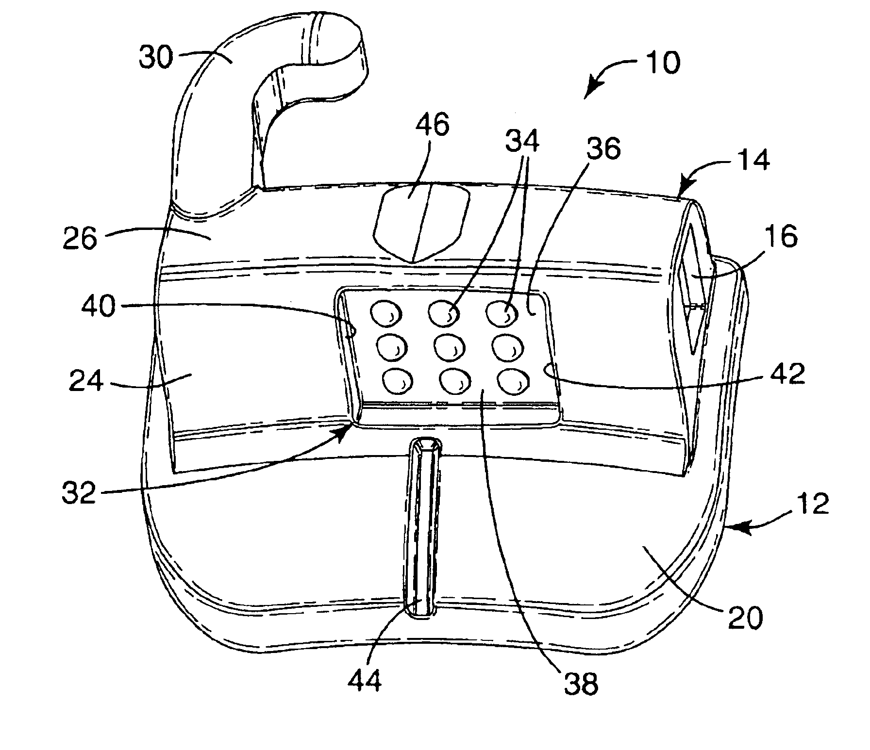
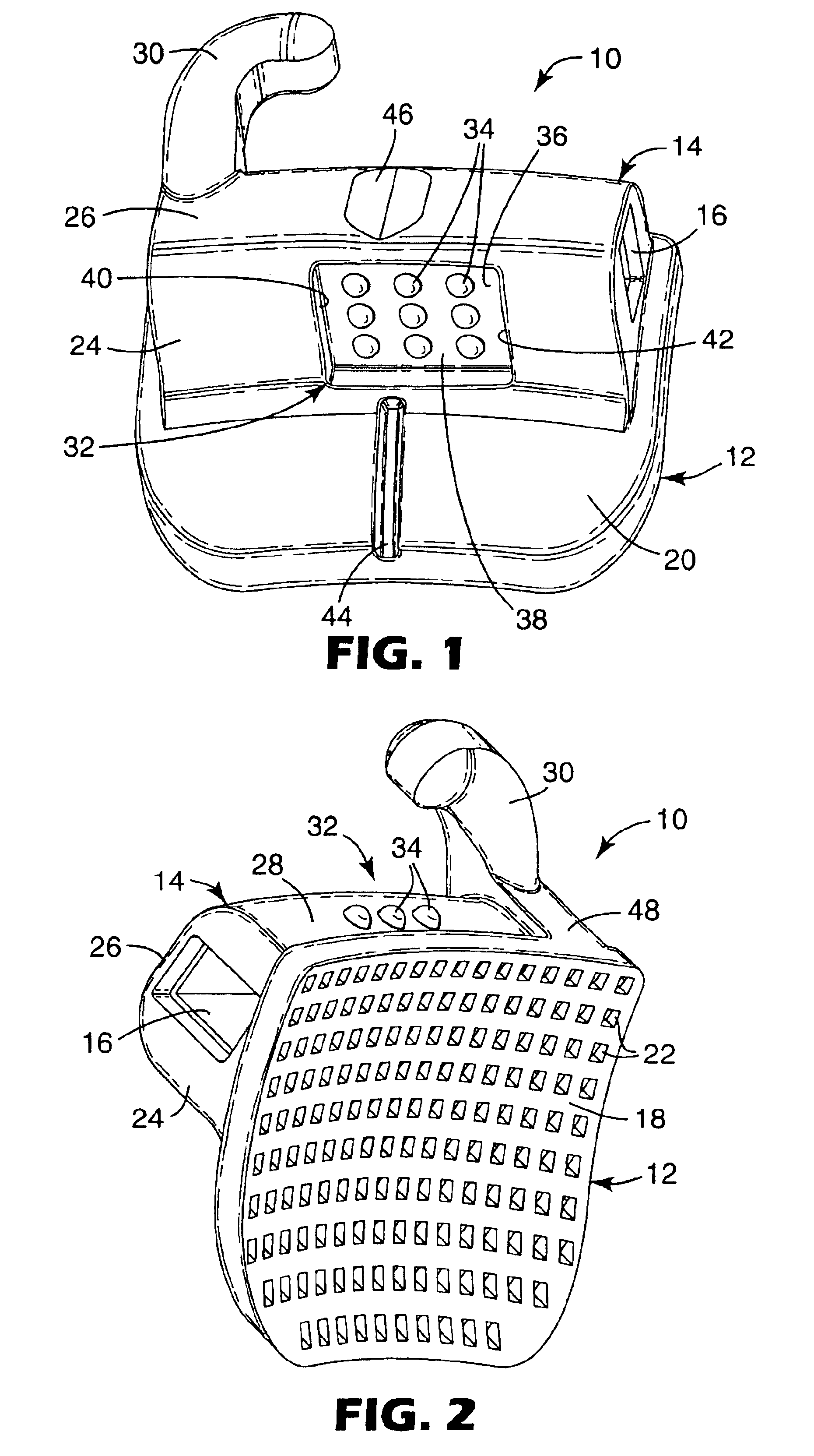
[0029]An orthodontic appliance according to one embodiment of the present invention is illustrated in FIGS. 1 and 2 and is broadly designated by the numeral 10. The appliance 10 includes a base 12 and a body 14 that is connected to the base 12. An elongated archwire slot 16 extends through the body 14 in a generally mesial-distal direction for receiving an archwire.

[0030]In more detail, the base 12 includes a first, tooth-facing side 18 that is illustrated in FIG. 2 and a second side 20 that is opposite to the first side 18. The second side 20 is shown in FIG. 1. In the illustrated example, the appliance 10 is adapted to be secured to a buccolabial side of a tooth (i.e., a side of the tooth facing the patient's cheeks or lips). Consequently, the first side 18 of the base 12 in this example can also be deemed a lingual side and the second side 20 can also be deemed a buccolabial side.

[0031]As shown in FIG. 2, the first side 18 of the base 12 is provided with a series of cavities 22 f...


PUM


Abstract

An orthodontic appliance that is adapted for bonding directly to the enamel surface of a patient's tooth has structure for enhancing placement of the appliance on the tooth surface. The structure facilitates gripping the appliance by a hand instrument so that the appliance does not unduly shift or rock during a bonding procedure. In certain aspects of the invention, the placement enhancement structure comprises one or more protrusions located along sides of the appliance, and optionally some of the protrusions are located within a recess that extends along an occlusal or gingival side of the appliance.

Description

BACKGROUND OF THE INVENTION[0001]1. Field of the Invention[0002]This invention broadly relates to an appliance that is secured to a tooth during the course of orthodontic treatment. More particularly, the present invention is directed to an orthodontic appliance having structure that facilitates manipulation, placement and removal of the appliance by the orthodontic practitioner.[0003]2. Description of the Related Art[0004]Orthodontia is a specialized field within the general subject area of dentistry. Orthodontic treatment involves movement of malpositioned teeth to correct locations along the dental arch. Orthodontic treatment can result in improved occlusion for the patient as well as a more pleasing aesthetic appearance.[0005]One type of orthodontic treatment involves the use of a set of components that are collectively known as “braces”. In this type of treatment, small slotted devices known as brackets are secured to the patient's anterior, cuspid and bicuspid teeth. An archwi...

Claims


Application Information

Patent Timeline
Patent Type & Authority Patents(United States)
IPC IPC(8): A61C7/28A61C7/00A61C7/14A61C7/16
CPCA61C7/146A61C7/282A61C7/16
Inventor KELLY, JOHN S.
Owner 3M INNOVATIVE PROPERTIES CO
Why Eureka
Try Eureka