Electrical connector assembly having improved grounding means

a technology of electrical connectors and grounding means, which is applied in the direction of coupling device details, coupling device connections, coupling protective earth/shielding arrangements, etc., can solve the problems of adversely affecting the reliable mating between the header and the receptacle connector, and achieve the effect of improving grounding and reducing insertion resistan

Inactive Publication Date: 2005-05-17
HON HAI PRECISION IND CO LTD
View PDF9 Cites 33 Cited by
  • Summary
  • Abstract
  • Description
  • Claims
  • Application Information

AI Technical Summary

Benefits of technology

[0007]An object of the present invention is to provide an electrical connector assembly having an improved grounding means which can reduce insertion resistance between a header and a receptacle connectors thereof.

Problems solved by technology

However, the contact springs of the header shielding plates extend in a direction opposite to the insertion direction of the receptacle connector, which increases insertion resistance of the receptacle connector, thereby adversely affecting a reliable mating between the header and the receptacle connectors.

Method used


Image

  • Electrical connector assembly having improved grounding means
  • Electrical connector assembly having improved grounding means
  • Electrical connector assembly having improved grounding means

Examples


Embodiment Construction

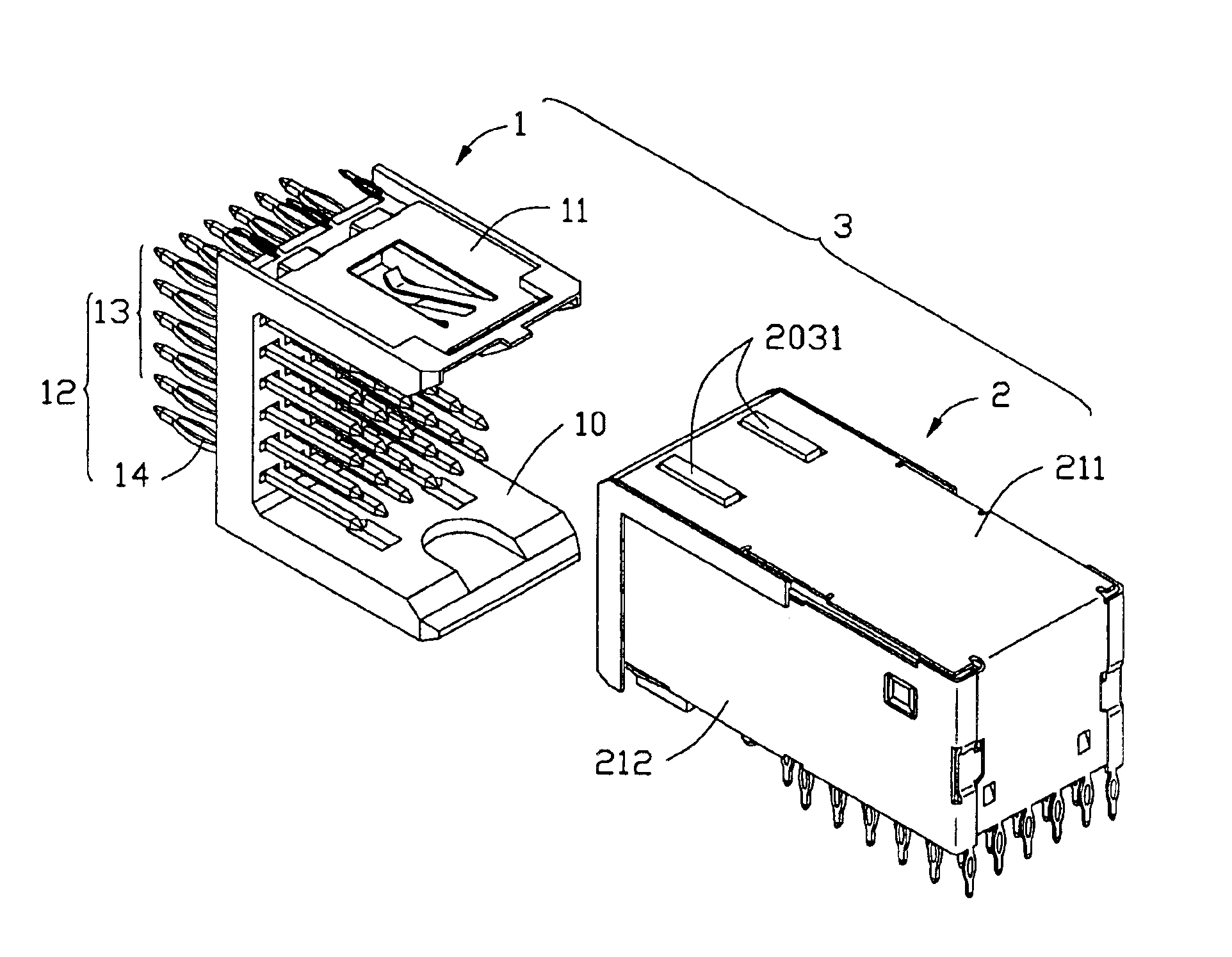
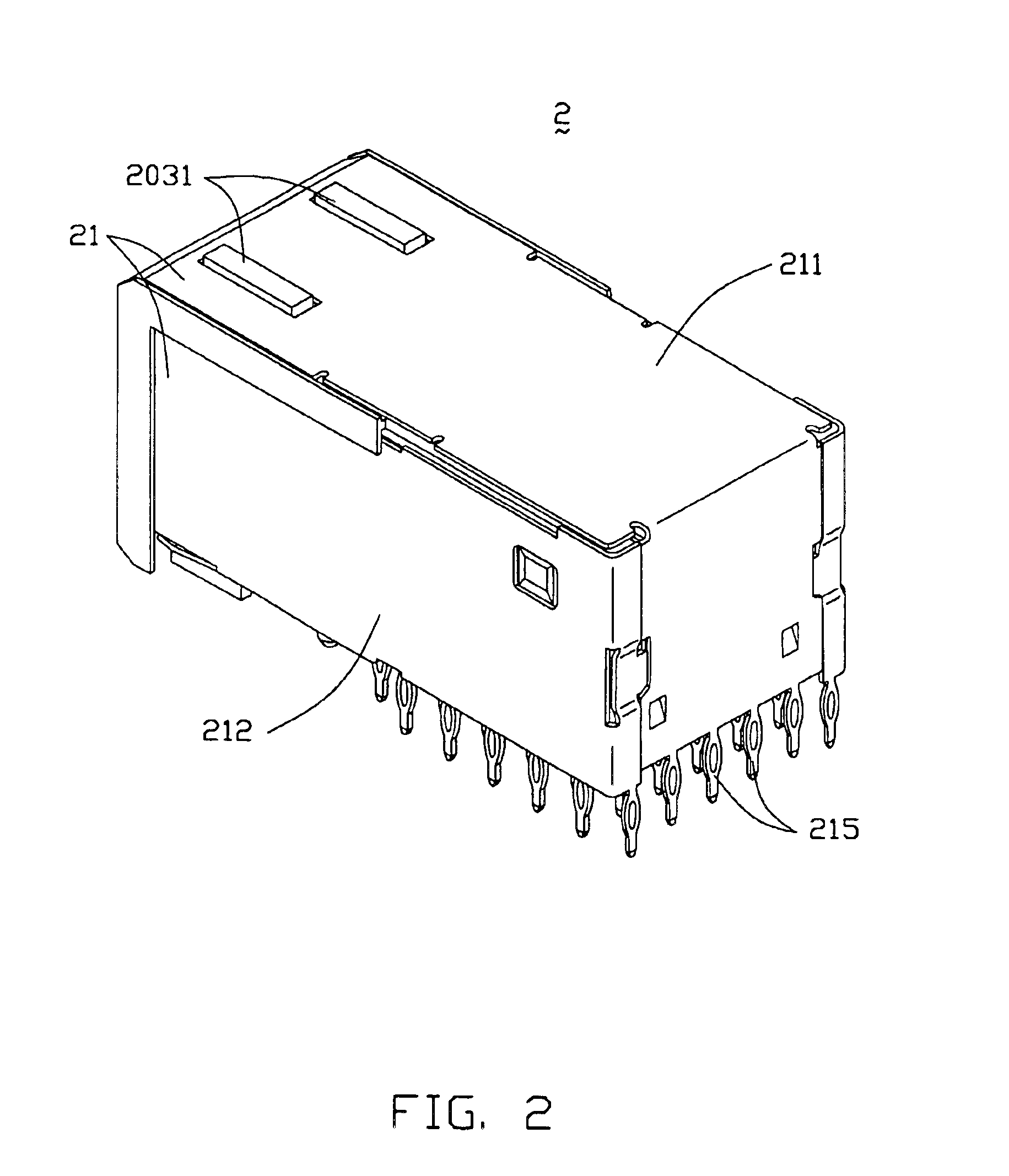
[0017]Referring to FIG. 7, an electrical connector assembly 3 in accordance with the present invention comprises a header connector 1 and a receptacle connector 2.

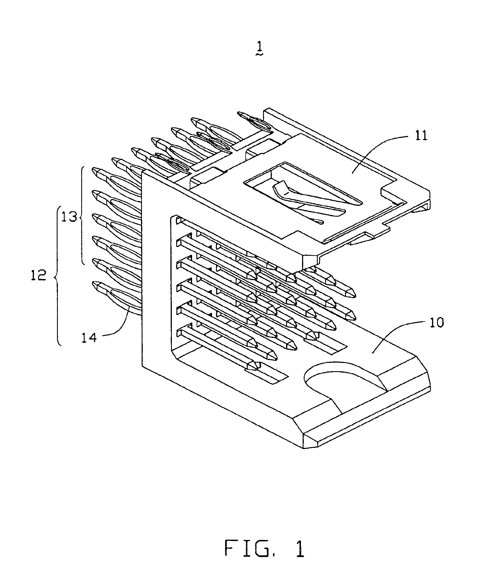
[0018]Referring to FIGS. 1 and 3, the header connector 1 comprises a header housing 10, a ground contact plate 11, and a plurality of header contacts 12. The header housing 10 comprises a base 100 and an upper and a lower sidewalls 101, 102 extending forwardly from an upper and a lower ends of the base 100. A mating space 103 is formed between the upper and the lower sidewalls 101, 102. The base 100 defines a plurality of rows of mounting apertures 104 therethrough in a mating direction of the header connector 1. The upper sidewall 101 defines a recess 1011 and a depression 1012 in an upper face (not labeled) thereof. The depression 1012 is located behind the recess 1011. A bottom surface 1014 of the depression 1012 is downwardly offset from the bottom surface 1013 of the recess 1011. A step surface 108 is formed between t...


PUM


Abstract

An electrical connector assembly (3) includes a header and a receptacle connectors (1,2). The header connector comprises a header housing (10) and a ground contact plate (11). The header housing has a base (100), a pair of sidewalls (101,102) extending from the base, and a mating space (103) formed between the sidewalls. The ground contact plate is attached to one of the sidewalls. The receptacle connector includes a receptacle housing (20) inserted into the mating space of the header housing, and a shield member (21) covering the receptacle housing. The ground contact plate has a contact beam (115) extending into the mating space through a notch (105) in the one sidewall along the insertion direction of the receptacle connector and contacting the shield member.

Description

BACKGROUND OF THE INVENTION[0001]1. Field of the Invention[0002]The present invention relates to an electrical connector assembly, and particularly to an electrical connector assembly having an improved grounding means.[0003]2. Description of Related Art[0004]It is common in electronic industry to provide a header connector having a plurality of male pins and mounted on a mother board, and a receptacle connector mounted on a daughter board. The receptacle connector has a plurality of receptacle contacts for electrically connecting with the male pins of the header connector. It is also known to shield the header and the receptacle connectors for protection from Electro-Magnetic Interference (EMI). For example, U.S. Pat. No. 5,433,618 shows such an electrical connector assembly comprising a header and a receptacle connectors. The header connector comprises a header housing having a bottom wall and two opposite side walls, a plurality of contact pins attached on the bottom wall, and he...

Claims


Application Information

Patent Timeline
Patent Type & Authority Patents(United States)
IPC IPC(8): H01R13/658
CPCH01R13/65807H01R13/6587H01R12/716
Inventor YU, HUNG-CHI
Owner HON HAI PRECISION IND CO LTD
Why Eureka
Try Eureka