Homocinetic joint

a technology of homocinetic joints and joints, applied in the direction of clutches, yielding couplings, rotary machine parts, etc., can solve the problem of low friction operating conditions

Inactive Publication Date: 2005-05-17
GKN LOBRO
View PDF19 Cites 12 Cited by
  • Summary
  • Abstract
  • Description
  • Claims
  • Application Information

AI Technical Summary

Benefits of technology

[0004]With reference to constant velocity joints, in particular constant velocity fixed ball joints wherein the width of the inner part exceeds the length of the windows of the cage in the circumferential direction, it is the object of the present invention to permit an assembly procedure which does not adversely affect the guidance of the balls in the widows of the cage and in the inner running grooves. Furthermore, it is the object of the present invention to prevent as far as possible the cage from being weakened.

Problems solved by technology

This results in low friction operating conditions.

Method used


Image

  • Homocinetic joint
  • Homocinetic joint
  • Homocinetic joint

Examples


Embodiment Construction

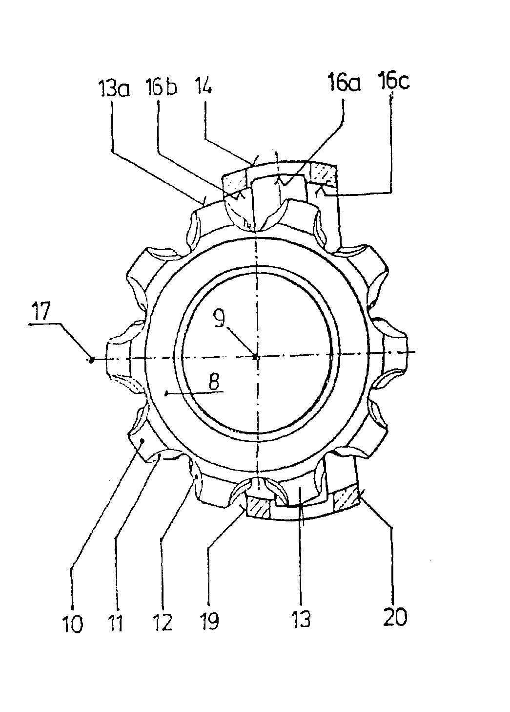
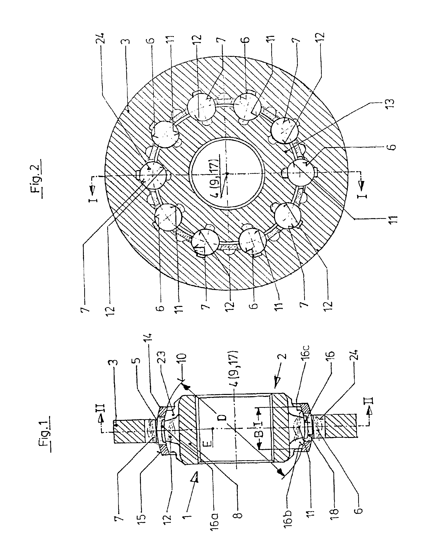
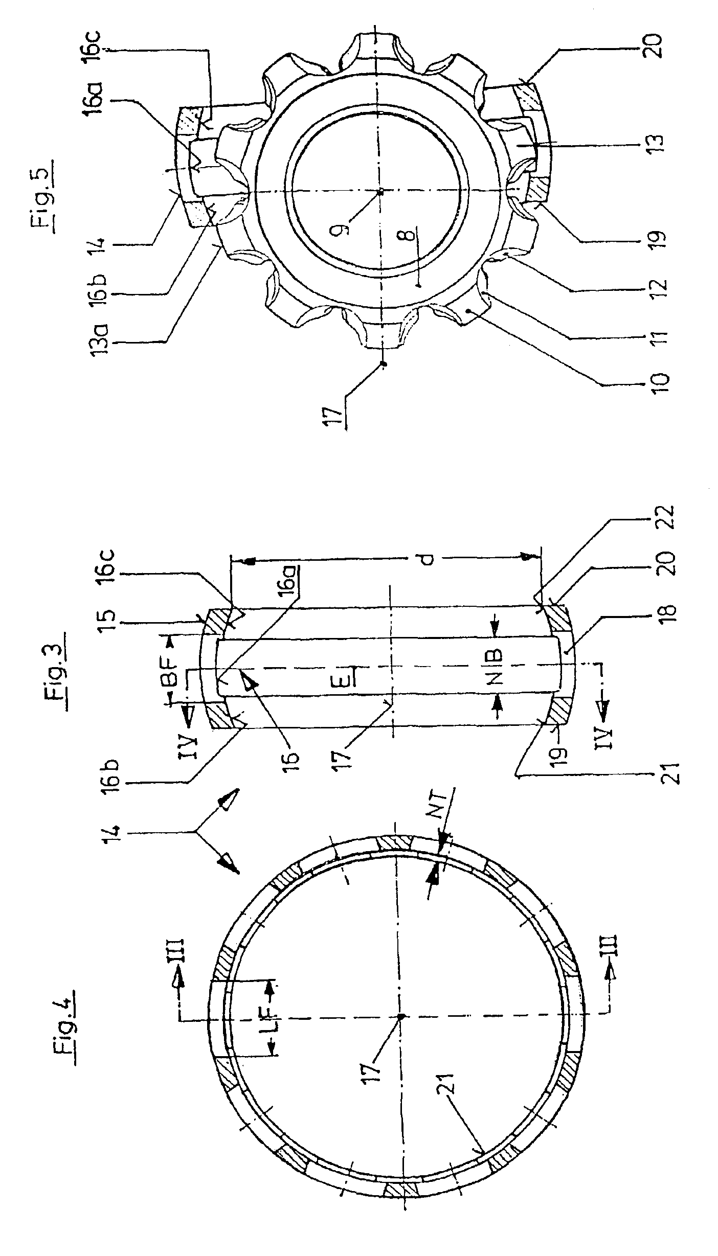
[0020]FIGS. 1 and 2 will be described jointly below. To be able to explain the way in which the parts are associated with one another and aligned relative to one another, the first end of the constant velocity joint has been given the reference number 1 and the second end the reference number 2. “End” does not refer to a definite end at a particular line or at a particular point, but it refers to the individual parts, taking into account their alignment and configuration.

[0021]The constant velocity joint is a fixed joint and comprises an outer part 3 with an aperture 5 which is centered on the longitudinal axis 4 of the outer part and extends through the outer part 3. In the aperture 5, there are arranged first outer running grooves 6 which are circumferentially distributed around the longitudinal axis 4 of the outer part and which start from the first end 1 in an undercut-free way, i.e. they extend curve-like. There are provided second outer running grooves 7 which alternate with t...


PUM


Abstract

The invention relates to a constant velocity joint having an outer part (3), an inner part (8), a cage (14) and balls (24). For the purpose of fitting the inner part (8) in the cage (14), there is provided a groove (16a) which can be entered by the inner part (8) by means of the web (13), so that the inner part (8) can be introduced into the cage (14), although the outer diameter of the inner part (8) is greater than that of the end aperture of the cage (14).

Description

BACKGROUND OF THE INVENTION[0001]The invention relates to a constant velocity joint. In particular, it relates to the inner part being assembled relative to the cage, with the cage being annular in shape and having a spherical outer face and a spherical inner face and with the cage, by means of its spherical inner face, being guided on a spherical outer face of the inner part of the constant velocity joint.[0002]In such constant velocity joints, the diameter of the spherical outer face of the inner part is greater than that of the end apertures of the cage which is guided by a suitable face on the spherical outer face. To be able to mount the cage, it is known, for example, to provide recesses which start from the end faces of the cage, whose number corresponds to the number of webs of the inner part between each two circumferentially adjoining inner running grooves and which permit the inner part to be slid axially into the cage. The recesses are arranged in the circumferential reg...

Claims


Application Information

Patent Timeline
Patent Type & Authority Patents(United States)
IPC IPC(8): F16D3/16F16D3/223F16D3/2237
CPCF16D3/2237F16D2003/22303Y10S464/906F16D2300/12F16D2003/22306
Inventor JACOB, ACHIMJACOB, WERNER
Owner GKN LOBRO
Why Eureka
Try Eureka