
Double-side lamination system

a lamination system and double-side technology, applied in the direction of mechanical control devices, process and machine control, instruments, etc., can solve the problems of undesirable lamination system and operational cost, and achieve the effect of reducing operational cost and minimizing waste material

Inactive Publication Date: 2005-05-17
JAPAN SERVO CO LTD
View PDF4 Cites 24 Cited by
  • Summary
  • Abstract
  • Description
  • Claims
  • Application Information

AI Technical Summary

Benefits of technology

[0010]It is an object of the present invention to solve the above problem and to provide a double-side lamination system capable of laminating in accordance with the various types of the cards by only itself, and lowering the operational cost while contributing to the environmental protection by minimizing the waste material.
[0017]Further, by applying the features of the present invention to a wasteless type double-side lamination system, it is possible to provide the double-side lamination system capable of lowering the operational cost while contributing to the environmental protection by minimizing the waste material.

Problems solved by technology

Such lamination system is undesirable in view of the operational cost and the protection of the environment, since the carrier is thrown away as a waste material.
Since the lamination system disclosed in U.S. Pat. No. 6,159,327 can be used for only double-side lamination, and can not be used for lamination in accordance with various types of the cards, there is a problem that a user of the lamination system is obliged to prepare a plurality of different lamination systems and to select and use one of them in accordance with the type of the cards to be issued.

Method used


Image

  • Double-side lamination system
  • Double-side lamination system
  • Double-side lamination system

Examples


Embodiment Construction

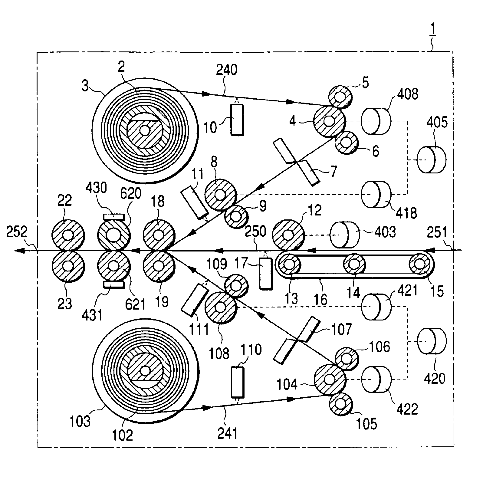
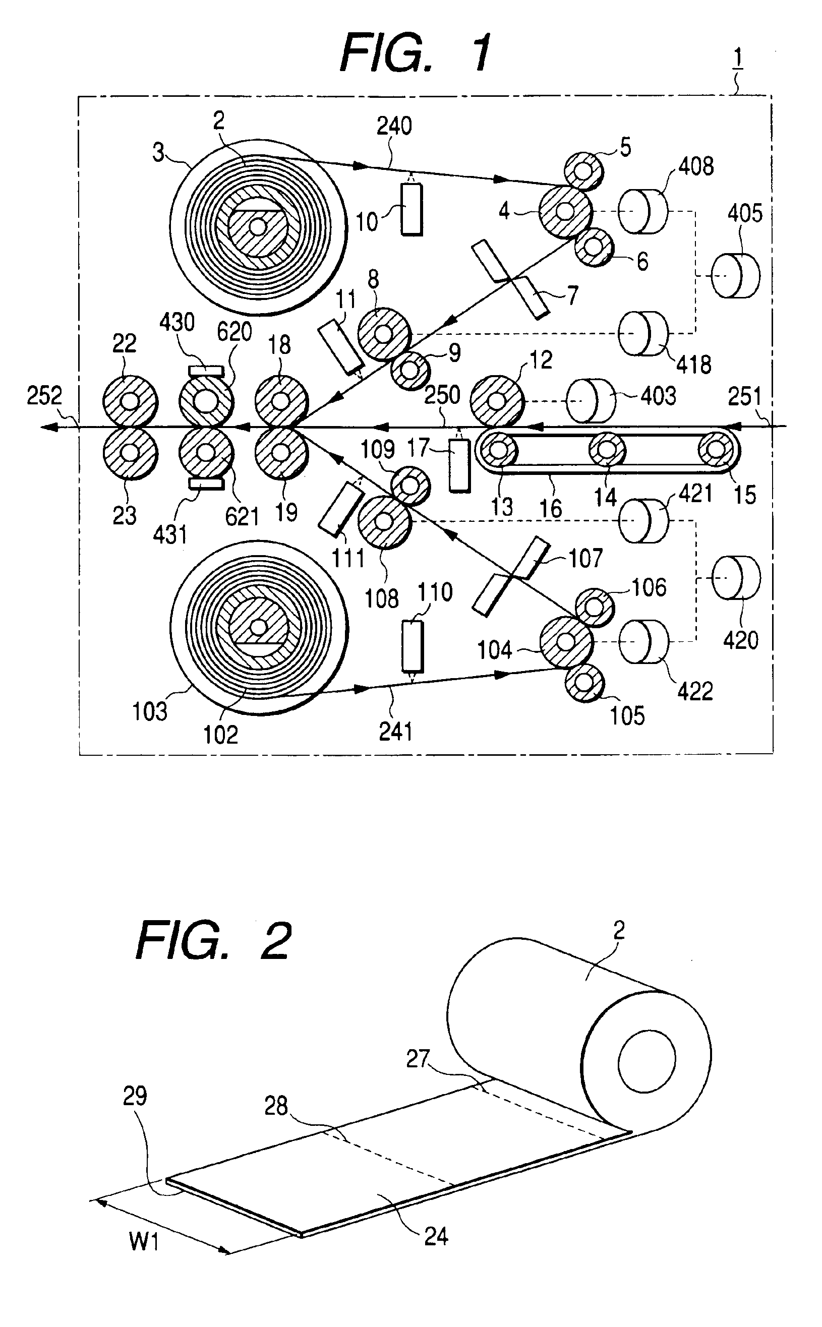
[0034]FIG. 1 is a schematic front view of a double-side lamination system 1 according to an embodiment of the present invention. The double-side lamination system 1 of which overall construction is shown in FIG. 1 is an system for making lamination on both surfaces of an ID card.

[0035]A transparent continuous laminate film with a heat adhesive layer on a surface is loaded in a form of a laminate roll 2 on a supply spindle 3. A leading edge of the continuous laminate film is drawn out from the laminate roll 2 and transferred along a film transfer path 240.

[0036]A laminate film supply monitoring sensor 10 composed of an optical sensor such as a reflective type optical sensor, for example, is provided along the film transfer path 240 and monitors the supply of the continuous laminate film.

[0037]The continuous laminate film is transferred, passing through rollers 4, 5 and 6, two cutting blades of a cutter 7, rollers 8 and 9, and under a film detection sensor 11 composed of an optical se...


PUM

PropertyMeasurementUnit
thicknessaaaaaaaaaa
pressureaaaaaaaaaa
temperaturesaaaaaaaaaa

Abstract

In a double-side lamination system having a thermocompression bonding device for laminating laminate films on both surfaces of a card by applying heat and pressure using a pair of heat rollers, a temperature measurement device for measuring temperatures of the heat rollers are provided, and whether the lamination system is in a double-side lamination mode in which laminations are carried out on both surfaces of the card, or in a single-side lamination mode in which lamination is carried out on one of the surfaces of the card, is automatically distinguished by comparing measured temperatures of the heat rollers at a predetermined time after turn-on of the power of the system with a predetermined reference temperature.

Description

[0001]This Nonprovisional application claims priority under 35 U.S.C. § 119(a) on Patent Application No(s). 2003-086643 filed in JAPAN on Mar. 27, 2003, the entire contents of which are hereby incorporated by reference.BACKGROUND OF THE INVENTION[0002]1. Field of the Invention[0003]The present invention concerns a double-side lamination system for thermocompression bonding of transparent films on both side surfaces of an ID card or the like.[0004]2. Description of the Prior Art[0005]Recently, ID cards of various types are being widely used. In order to protect an ID card from tampering or to improve the life of the ID card, a transparent film of about 30 μm in thickness is laminated by a thermocompression bonding on a surface of the ID card on which information data are printed. Lamination systems such as disclosed in U.S. Pat. No. 5,807,461, U.S. Pat. No. 5,783,024 and U.S. Pat. No. 6,159,327 are known as systems suitable for such lamination.[0006]In the lamination system disclosed...

Claims


Application Information

Patent Timeline
Patent Type & Authority Patents(United States)
IPC IPC(8): B32B37/18B32B37/14B29C63/02B29L7/00B29L9/00
CPCB32B37/182B32B37/185Y10T156/1741B32B2425/00B32B2429/00B32B2309/02
Inventor SASAKI, NAOTAKAKAWAMATA, SHUNICHISUGAYA, KENJIITO, HIDEAKI
Owner JAPAN SERVO CO LTD
Learn More