Modified contoured crushable structural members and methods for making the same

a technology of contoured crushing and structural members, applied in the direction of synthetic resin layered products, non-electric welding apparatus, packaging, etc., can solve the problems of not having additional components or elements in the member, and the application of such materials is quite limited

Inactive Publication Date: 2005-05-17
DELPHI TECH INC
View PDF177 Cites 36 Cited by
  • Summary
  • Abstract
  • Description
  • Claims
  • Application Information

AI Technical Summary

Problems solved by technology

Such combinations, however, have been generally limited to relatively flat structures and so applications of such materials have been quite limited.
As well, the structural members have not contained additional components or elements that would enhance their use for applications other than just solely as structural members.

Method used


Image

  • Modified contoured crushable structural members and methods for making the same
  • Modified contoured crushable structural members and methods for making the same
  • Modified contoured crushable structural members and methods for making the same

Examples


example 1

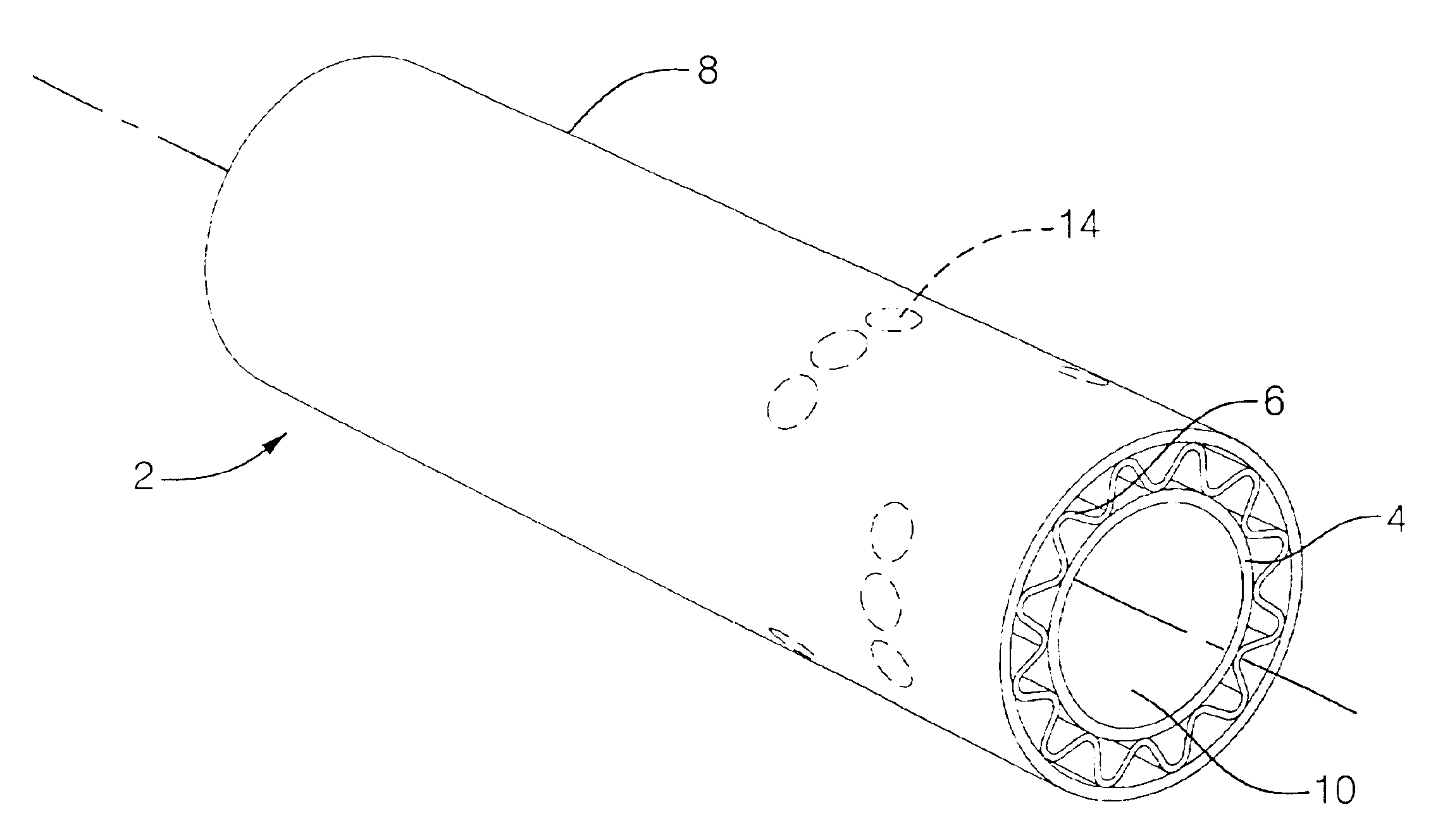
[0099]A hollow, cylindrical structural member with a hexagonal cross-section was made according to following process. A thin coat of a release material (Frekote 700NC or Axel EM606SL / SP) was applied to a 0.3395 inch diameter hexagonal aluminum mandrel with a length of 48 inches.

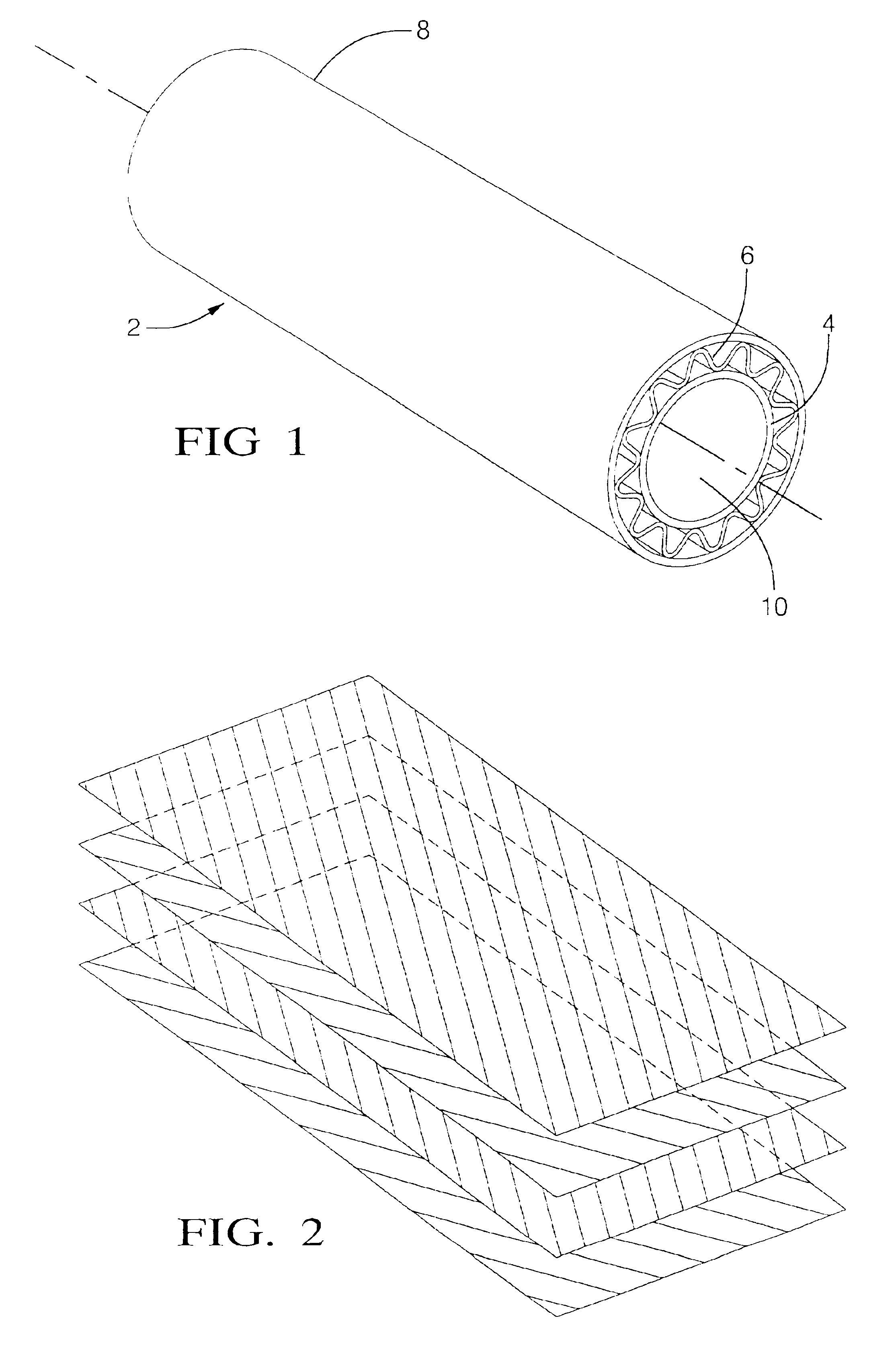
[0100]A single coating layer was prepared by laying a Decron / Telfon woven fabric with dimensions of 2.39″×4.0″ and a 7781 glass cloth with dimensions of 2.39″×3.75″ end to end. Enough alternating pieces were layed end-to-end to make a 2.39″ wide and 40″ long layer. This layer was then roll wrapped over the mandrel.

[0101]A single sheet of anisotropic carbon fibers in an epoxy-based resin was cut with measurements of about 2.44 inches in width and about 40 inches in length. The individual sheet was cut with a fiber angle of 90 degrees. The sheet was roll wrapped over the coating layer.

[0102]Fourteen pairs of B-stage prepreg laminate sheets (28 individual sheets) containing anisotropic carbon fibers in an epoxy-...

example 2

[0108]A hollow, cylindrical structural member with a circular cross-section was made according to following process. A thin coat of a release material (Frekote 700NC or Axel EM606SL / SP) was applied to a 0.729 inch diameter circular steel mandrel with a length of 64 inches.

[0109]A pair of B-stage prepreg laminate sheets (2 individual sheets) containing anisotropic carbon fibers in an epoxy-based resin were cut with measurements of about 2.31 to 2.34 inches in width and about 60 inches in length. The individual laminate sheets were overlaid so the fibers in successive sheets were symmetric and balanced at angles of ±80 degrees. The air between the stacked sheets was removed by using a roller.

[0110]21 individual sheets of B-stage prepreg laminate sheets containing anisotropic carbon fibers in an epoxy-based resin were cut then with measurements of about 2.37 to 2.99 inches in width and about 60 inches in length. The individual laminate sheets were overlaid so the fibers in successive s...


PUM

PropertyMeasurementUnit
anglesaaaaaaaaaa
anglesaaaaaaaaaa
widthaaaaaaaaaa

Abstract

Modified contoured crushable structural members and methods for making the same are described. The contoured structural members comprise composite or metal materials sandwiching a support or stabilizing structure. The structural members are made crushable by incorporating an initiator into the structural members. The structural member crushes at the location of the initiator by absorbing the energy of an exerting load. The modified structure is provided by attaching additional structural components or elements to the end or outside of the structural member or by modifying the shape of the structural member. With a modified, contoured, crushable, and generally non-flat structure, applications and uses for the structural members of the present invention are nearly limitless.

Description

REFERENCES TO RELATED APPLICATIONS[0001]This application claims priority from U.S. provisional patent application No. 60 / 216,636 filed Jul. 7, 2000, the entire disclosure of which is incorporated herein by reference.FIELD OF THE INVENTION[0002]The present invention relates to structural members and methods for making the same. In particular, the present invention relates to modified contoured crushable composite parts and methods for making the same.BACKGROUND OF THE INVENTION[0003]In recent years there has been an increasing emphasis on the use of lightweight composite materials. One application, for example, has been their use to improve the efficiency of motor vehicles. To that end, the United States Government and the U.S. Council for Automotive Research (USCAR)—which represents Daimler Chrysler, Ford, and General Motors have partnered to form the Partnership for a New Generation of Vehicles (PNGV). One goal of PNGV is to develop technology, such as composite technology, that ca...

Claims


Application Information

Patent Timeline
Patent Type & Authority Patents(United States)
IPC IPC(8): B21C37/15B32B1/00B32B1/08B32B15/04B32B15/01B32B3/12B32B15/08B29C70/04B32B3/30B29C70/32B32B3/28B29D24/00B62D21/09B62D21/00B65H75/04B65H75/10F16L9/00F16L9/02F16L9/19F16L9/18B29C70/06B29D99/00B32B3/10B32B3/26B32B27/04F16L7/00
CPCB21C37/154B29C70/32B29D24/002B29D24/004B29D99/0035B32B1/08B32B3/12B32B3/28B32B3/30B32B15/01B32B15/04B32B15/08B32B27/04B62D21/00B62D21/09B62D29/001B62D29/005B65H75/10F16L7/00F16L9/003F16L9/006F16L9/02F16L9/18F16L9/19B62D29/004B21C37/15A63B59/0092Y10T428/139B29L2031/324B65H2701/5114Y10T428/13Y10T29/53652Y10T428/12493Y10T428/1241Y10T428/1234Y10T428/24149Y10T428/24165Y10T428/12375Y10T428/12361A63B60/54B62D21/15
Inventor OBESHAW, DALE FRANCIS
Owner DELPHI TECH INC
Why Eureka
Try Eureka