Dynamoelectric device air flow baffle shaped to increase heat transfer

a technology of air flow and dynamoelectric devices, which is applied in the direction of windings, magnetic circuit rotating parts, magnetic circuit shapes/forms/construction, etc., can solve the problems of disadvantaged prior art baffle designs, lower air flow rate and velocity, etc., to reduce separation, reduce/eliminate separation, and improve the inlet flow into the fan

Inactive Publication Date: 2005-05-17
NIDEC MOTOR CORP
View PDF3 Cites 11 Cited by
  • Summary
  • Abstract
  • Description
  • Claims
  • Application Information

AI Technical Summary

Benefits of technology

[0010]The air flow baffle of the present invention overcomes disadvantages associated with prior art air flow baffles. The baffle of the invention decreases the potential of separation occurring in the flow of air directed from the outer peripheral edge of the baffle radially inwardly across the disk shape of the baffle, and also reduces the potential of separation occurring in the air flow that is drawn across the disk shape and around the baffle inner edge through the baffle center hole.
[0015]The baffle of the present invention operates in basically the same manner as prior art baffles in that, on rotation of the rotor shaft and the fan, a flow of cooling air is drawn through and across the rotor and stator on one side of the baffle and through the baffle center hole to the fan on the opposite side of the baffle. However, the flow of air drawn across the outer periphery of the stator toward the baffle is drawn across the annular concave surface of the baffle at the baffle plate outer perimeter. The annular concave surface of the baffle receives the axial flow of air across the outer perimeter of the stator and redirects the flow, radially inwardly between the stator wiring end turns and the flat annular portion of the plate. The curvature of the annular concave surface redirects the flow of air from an axial direction, to a radially inward direction without creating the pressure losses of the air flow that was caused by the right angle connection of the outer cylindrical rim and outer perimeter edges of the baffle plate of the prior art.
[0016]The radially inwardly directed flow of air then passes over the convex surface of the lip surrounding the plate center hole and is directed around the lip and through the center hole to the fan on the opposite side of the plate. The convex surface of the lip functions to reduce separation of the air flow around the plate inner edge and the creation of a separation region in the air flow directed through the center hole from that created by the prior art baffle plates that have right angle edges of the baffle plate around the center hole. Reducing / eliminating separation here results in better inlet flow into the fan. In addition, the projection of the lip concave surface from the baffle plate toward the winding end turns of the stator reduces the cross-sectional area of the air flow in the area between the baffle lip and the stator end turns. This reduction in the spacing between the baffle lip and the end turns increases the velocity of the air flow drawn between the baffle plate and stator windings, thereby increasing cooling efficiency.
[0017]Thus, by reducing air flow separation and the associated pressure losses and increasing the velocity of air flow between the stator and the baffle and creating better fan inlet flow conditions, the air flow directing baffle of the present invention increases the cooling efficiency of the baffle of the invention over that of prior art baffles.

Problems solved by technology

Prior art baffle designs have been found to be disadvantaged in that they employ right angle corners where the outer perimeter rim of the baffle joins the flat baffle disk as well as right angle corners at the inner edge of the baffle surrounding the baffle center hole.
The right angle corners have a tendency to cause flow separation of the cooling air drawn through the casing shell, causing an undesirable pressure loss and resulting in lower air flow rates and velocity.

Method used


Image

  • Dynamoelectric device air flow baffle shaped to increase heat transfer
  • Dynamoelectric device air flow baffle shaped to increase heat transfer
  • Dynamoelectric device air flow baffle shaped to increase heat transfer

Examples


Embodiment Construction

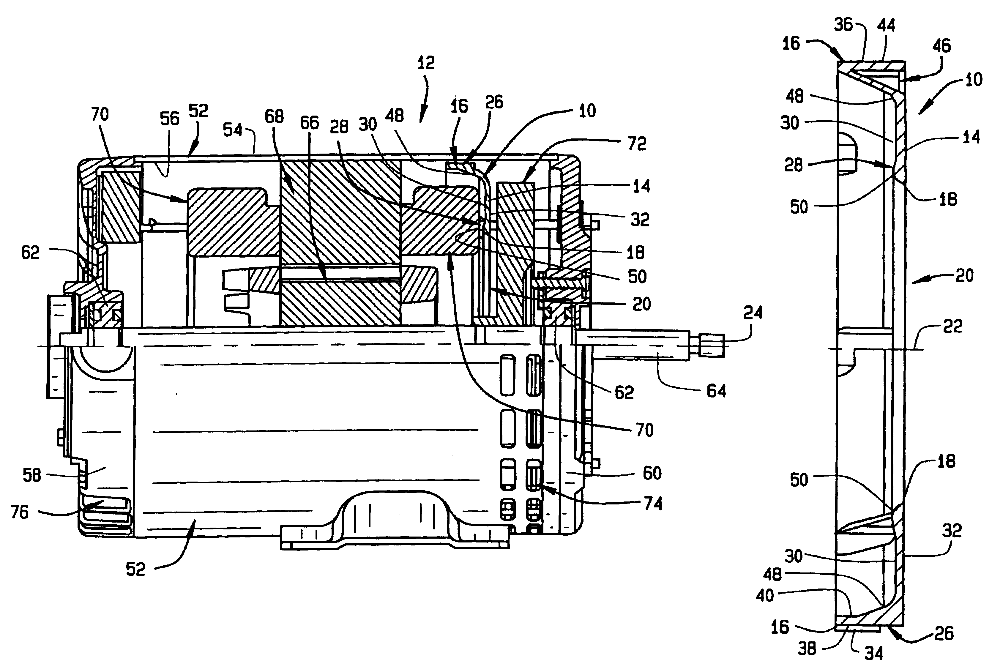
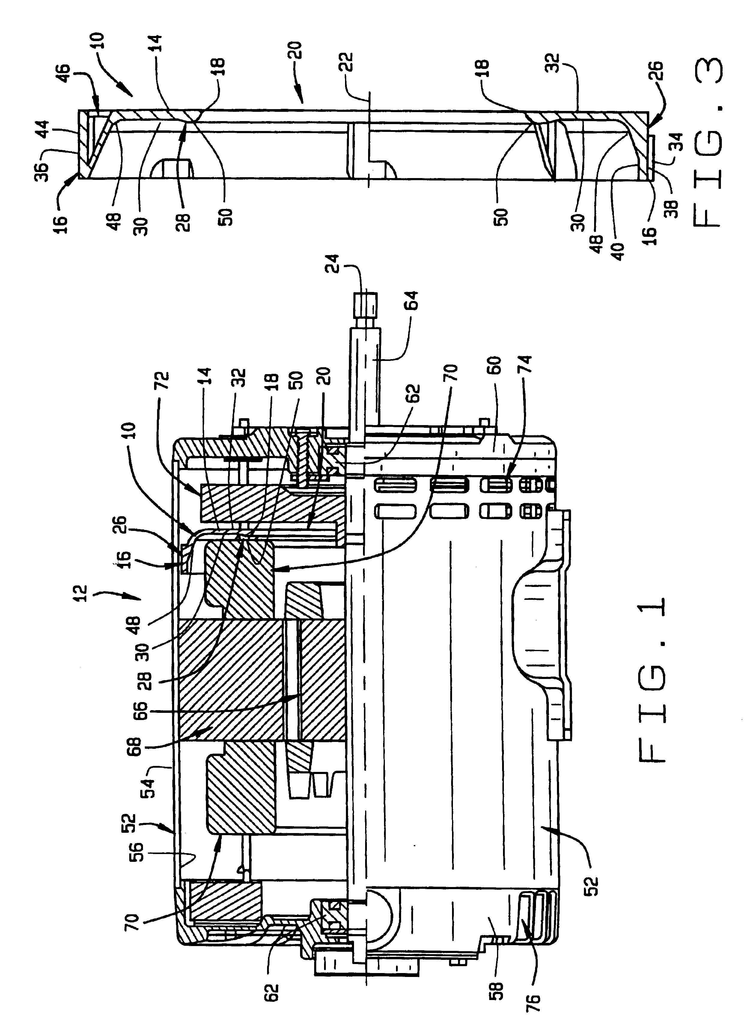
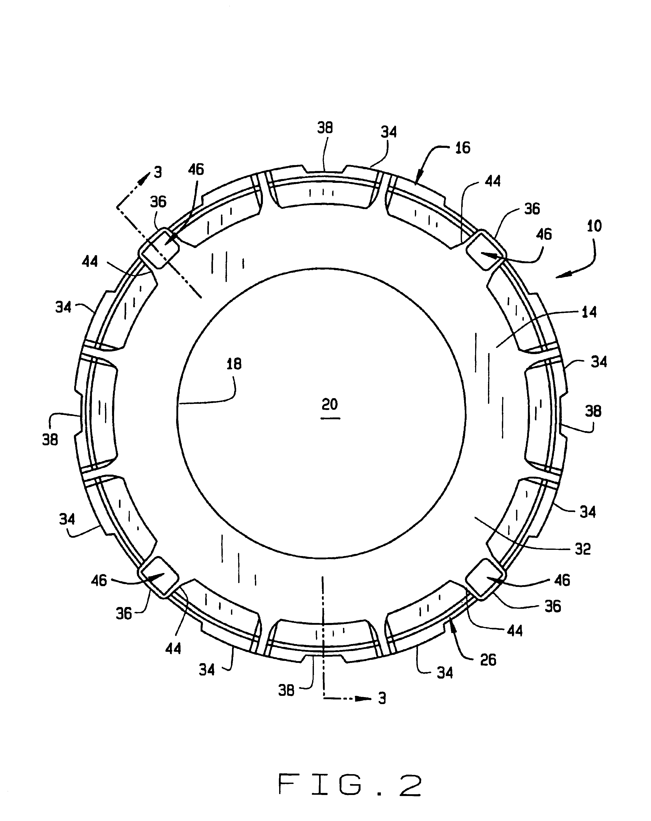
[0023]FIG. 1 shows a sectioned view of the air flow baffle 10 of the present invention employed in an electric motor 12 dynamoelectric device. FIGS. 2 to 4 show the baffle 10 removed from the device. Although the baffle 10 is to be described in use in an electric motor dynamoelectric device, it should be understood that the baffle is equally well suited for use in other dynamoelectric devices. It is not intended that the description of the baffle with an electric motor limit the scope of protection for the baffle to only use in an electric motor dynamoelectric device.

[0024]The air baffle 10 of the invention can be stamped from metal, molded of plastic, or manufactured by other equivalent methods and of other equivalent materials. The baffle 10 is basically a circular disk or plate 14 having a circular outer perimeter edge 16 and a circular inner edge 18 surrounding a center hole 20 of the baffle. The center hole 20 has a center axis 22 that is co-axial with a center axis 24 of the e...


PUM


Abstract

A dynamoelectric device cooling air flow baffle is given a shape that increases its heat transfer and cooling efficiency by providing the baffle with an annular concave surface around its outer perimeter edge that redirects air flow radially inwardly around stator winding end turns while reducing separation of the air flow and also directs the cooling air flow around an inner edge of a center hole of the baffle while reducing separation of the air flow and increasing air flow velocity, thereby efficiently cooling the stator assembly of the dynamoelectric device.

Description

BACKGROUND OF THE INVENTION[0001](1) Field of the Invention[0002]The present invention pertains to an air flow baffle used in an dynamoelectric device that has a novel shape that increases air cooling of the device. More specifically, the present invention pertains to an air flow baffle that is positioned in the casing shell of a dynamoelectric device between the stator and a cooling fan of the device, where the air flow baffle directs a flow of cooling air across the dynamoelectric device while reducing flow separations and pressure losses in the air flow and thereby more efficiently cools the dynamoelectric device.[0003](2) Description of Related Art[0004]Many dynamoelectric devices such as appliance motors for dishwashers, clothes washers and dryers and whirlpool baths utilize fans mounted on their rotor shafts to provide for air cooling of the stators and rotors of the motors during their operation. Typically, the fan is mounted at one axial end of the device and is shaped to pu...

Claims


Application Information

Patent Timeline
Patent Type & Authority Patents(United States)
IPC IPC(8): H02K9/06H02K9/04
CPCH02K9/06
Inventor BOSTWICK, PETER K.JONES, PATRICK M.
Owner NIDEC MOTOR CORP
Why Eureka
Try Eureka